Nissan Rogue Service Manual: Symptom diagnosi
NOISE, VIBRATION, AND HARSHNESS (NVH) TROUBLESHOOTING
NVH troubleshooting - engine noise
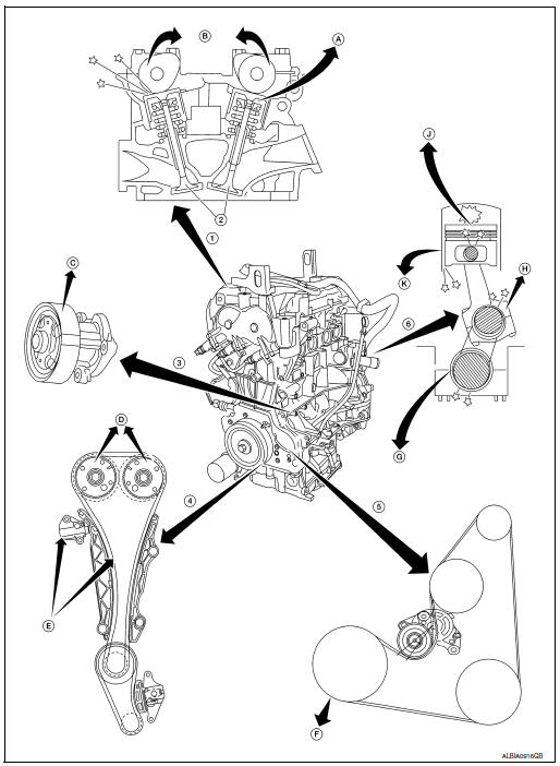
- Valve mechanism
- Intake and exhaust valve
- Water pump
- Timing chain
- Drive belt
- Rotation mechanism
- Tappet noise
- Camshaft bearing noise
- Water pump noise
- VTC noise
- Timing chain and chain tensioner noise
- Drive belt noise (slipping)
- Main bearing noise
- Connecting rod bearing noise
- Piston pin noise
- Piston slap noise
Use the chart below to help you find the cause of the symptom
- Locate the area where noise occurs.
- Confirm the type of noise.
- Specify the operating condition of engine.
- Check specified noise source.
If necessary, repair or replace these parts.
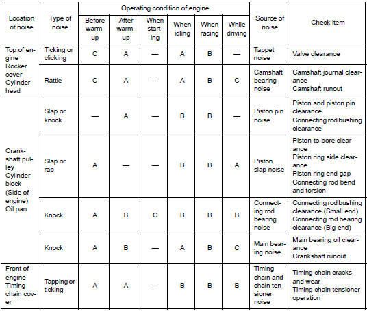
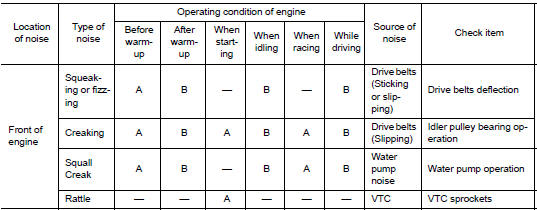
A: Closely related B: Related C: Sometimes related ŌĆö: Not related
 Liquid Gasket
REMOVAL OF LIQUID GASKET SEALING
After removing the bolts and nuts, separate the mating surface and
remove the liquid gasket using Tool (A).
Tool Number : KV10111100 (J-37228)
CAUTION:
Be c ...
 Preparation
Special service tools
The actual shape of the tools may differ from those illustrated here.
Tool number
(TechMate No.)
Tool name
Description
ŌĆö
(J-48891)
Spark p ...
Other materials:
Installing front license plate
Installing front license plate
Use the following steps to mount the front license
plate:
Before mounting the license plate, confirm that
the following parts are enclosed in the plastic
bag:
License plate bracket
License plate bracket (J-nut) screws x 2
License plat ...
Unit removal and installation
TRANSFER ASSEMBLY
Exploded View
1 Transfer assembly
: N┬Ęm (kg-m, ft-lb)
*: Apply anti-corrosion oil.
Removal and Installation
NOTE:
When removing components such as hoses, tubes/lines, etc., cap or plug openings
to prevent fluid from spilling.
REMOVAL
Remove front drive shaf ...
Structure and operation
Positive Crankcase Ventilation
This system returns blow-by gas to the intake manifold.
The positive crankcase ventilation (PCV) valve is provided to conduct crankcase
blow-by gas to the intake
manifold.
During partial throttle operation of the engine, the intake manifold sucks the
bl ...
