Nissan Rogue Service Manual: Liquid Gasket
REMOVAL OF LIQUID GASKET SEALING
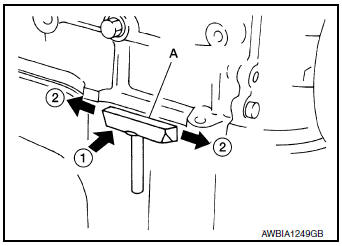
- After removing the bolts and nuts, separate the mating surface and remove the liquid gasket using Tool (A).
Tool Number : KV10111100 (J-37228)
CAUTION: Be careful not to damage the mating surfaces.
- In areas where the cutter is difficult to use, use a plastic hammer to lightly tap (1) the cutter where the liquid gasket is applied. Use a plastic hammer to slide (2) the cutter by tapping on the side.
CAUTION: Do not damage the mating surfaces.
LIQUID GASKET APPLICATION PROCEDURE
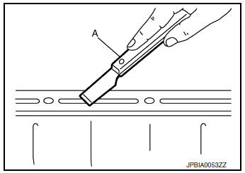
- Using suitable tool (A), remove old liquid gasket adhering to the liquid gasket application surface and the mating surface.
- Remove liquid gasket completely from the groove of the liquid gasket application surface, bolts, and bolt holes.
- Thoroughly clean the mating surfaces and remove adhering moisture, grease and foreign materials.
- Attach liquid gasket tube to the suitable tool.
Use Genuine Silicone RTV Sealant, or equivalent. Refer to GI-22, "Recommended Chemical Products and Sealants".
- Apply liquid gasket without gaps to the specified location according to the specified dimensions.
- If there is a groove for liquid gasket application, apply liquid gasket to the groove.
- As for bolt holes (B), normally apply liquid gasket inside the
holes. Occasionally, it should be applied outside the holes.
Check to read the text of this manual.
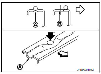
(A) : Groove
 : Inside bolt hole
- Within five minutes of liquid gasket application, install the mating component.
- If liquid gasket protrudes, wipe it off immediately.
- Do not retighten bolts or nuts after the installation.
- After 30 minutes or more have passed from the installation, fill engine oil and engine coolant.
CAUTION: If there are specific instructions in the procedures contained in this manual concerning liquid gasket application, observe them.
 Special Cautions to Ensure the Safe Disposal of Sodium-filled Exhaust
Valves
Special Cautions to Ensure the Safe Disposal of Sodium-filled Exhaust
Valves
Handling and disposal of sodium-filled exhaust valves requires special
care and consideration. Under conditions such as breakage with
subsequent contact with water, metal sodium which lines the inne ...
 Symptom diagnosi
NOISE, VIBRATION, AND HARSHNESS (NVH) TROUBLESHOOTING
NVH troubleshooting - engine noise
Valve mechanism
Intake and exhaust valve
Water pump
Timing chain
Dr ...
Other materials:
P0137 HO2S2
DTC Description
DTC DETECTION LOGIC
The heated oxygen sensor 2 has a much longer switching time
between rich and lean than the air fuel ratio (A/F) sensor 1. The oxygen
storage capacity of the three way catalyst (manifold) causes the
longer switching time. To judge the malfunctions of heated ox ...
Precaution
Precaution for Supplemental Restraint System (SRS) "AIR BAG" and "SEAT
BELT
PRE-TENSIONER"
The Supplemental Restraint System such as “AIR BAG” and “SEAT BELT
PRE-TENSIONER”, used along
with a front seat belt, helps to reduce the risk or severity of injury to the
...
CVT oil warmer
Exploded View
Transaxle assembly
CVT oil warmer
: N·m (kg-m, in-lb)
Removal and Installation
REMOVAL
WARNING:
Do not remove the radiator cap when the engine is hot. Serious burns could occur
from high pressure
engine coolant escaping from the radiator. Wrap a thick cloth around ...
