Nissan Rogue Service Manual: Preparation
Special service tools
The actual shape of the tools may differ from those illustrated here.
|
Tool number (TechMate No.) Tool name |
Description | |
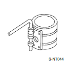
| ÔÇö (J-48891) Spark plug socket | 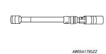 |
Removing and installing spark plug |
| KV10111100 (J-37228) Seal cutter | 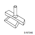 |
Removing oil pan and timing chain case |
| KV10112100 (BT-8653-A) Torque angle meter | 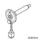 |
Tightening bolts for bearing cap, cylinder head, etc. |
Commercial service tools
|
Tool number (TechMate No.) Tool name |
Description |
|
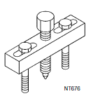
| Pulley puller |
|
Removing crankshaft pulley |
| Piston ring compresso |
|
Installing piston assembly into cylinder bore |
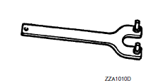
| Pulley holder |
|
Crankshaft pulley removing and installing |
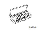
| Valve seat cutter set |
|
Finishing valve seat dimensions |
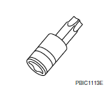
| Socket |
|
Removing and installing flywheel Size: T55 |
| Piston ring expander |
|
Removing and installing piston ring |
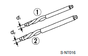
| Valve guide drift |
|
Removing and installing valve guide
Intake & Exhaust: a: 9.5 mm (0.374 in) dia. b: 5.5 mm (0.217 in) dia. |
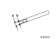
| Valve guide reamer |
|
Intake & Exhaust: |
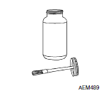
| Anti-seize lubricant i.e.: (PermatexTM 133AR or equivalent meeting MIL specification MIL-A-907) |
|
Lubricating oxygen sensor thread cleaning tool when reconditioning exhaust system threads |
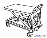
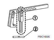
| Manual lift table caddy |
|
Removing and installing engine |
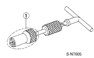
| KV10107902 (J-38959) Valve oil seal puller with adapter (1) |
|
Removing valve oil seal |
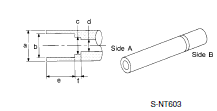
| KV10115600 (J-38958) Valve oil seal drift |
|
Installing valve oil seal Use side A. Unit: mm (in) |
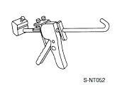
| Tube presser |
|
Pressing the tube of liquid gasket |
| Exhaust gas sensor wrench |
|
Removing exhaust gas sensor |
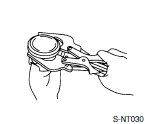
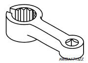
| KV10116200 (J-26336-A) Valve spring compressor 1. KV10115900 (J-26336-20) Attachment 2. KV10109220 ( ÔÇö ) Adapter |
|
Disassembling valve mechanism Part (1) is a component of KV10116200 (J- 26336-A), but part (2) is not. |
 Symptom diagnosi
NOISE, VIBRATION, AND HARSHNESS (NVH) TROUBLESHOOTING
NVH troubleshooting - engine noise
Valve mechanism
Intake and exhaust valve
Water pump
Timing chain
Dr ...

Other materials:
AM radio reception
AM signals, because of their low frequency, can
bend around objects and skip along the ground.
In addition, the signals can be bounced off the
ionosphere and bent back to earth. Because of
these characteristics, AM signals are also subject
to interference as they travel from transmitter
to r ...
Preparation
Special Service Tool
The actual shape of the tools may differ from those tools illustrated here.
Tool number
(TechMate No.)
Tool nam
Description
ÔÇö
(J-50190)
Signal Tech II
Activate and display TPMS transmitter IDs
Display tire ...
Fuel pressure
Work Procedure
FUEL PRESSURE RELEASE
1.FUEL PRESSURE RELEASE
With CONSULT
Turn ignition switch ON.
Perform ÔÇťFUEL PRESSURE RELEASEÔÇŁ in ÔÇťWORK SUPPORTÔÇŁ mode of ÔÇťENGINEÔÇŁ
using CONSULT.
Start engine.
After engine stalls, crank it two or three times to ...
