Nissan Rogue Service Manual: Luggage room lamp
Removal and Installation
REMOVAL
- Insert a suitable tool (A) into the gap between the luggage lower
finisher (RH) (2) and the top of luggage room lamp (1) to release
the pawl.
 : Pawl
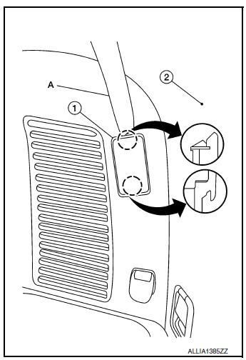
- Disconnect the harness connector from the luggage room lamp and remove.
INSTALLATION
Installation is in the reverse order of removal.
Bulb Replacement
WARNING: Do not touch the glass surface of a bulb while it is lit or right after being turned OFF to prevent burns.
CAUTION:
- Do not touch the glass of bulb directly by hand. Keep grease and other oily substances away from bulb surface.
- Do not leave bulb out of lamp reflector for a long time because dust, moisture, smoke, etc. may affect the performance of lamp.
- Remove luggage room lamp. Refer to INL-61, "Removal and Installation".
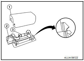
- Release pawls using a suitable tool and remove luggage room
lamp cover (1).: Pawl
- Push the tab to release one bulb end, then grasp the luggage room lamp bulb (3) and pull out the second end to remove.
- Install luggage room lamp bulb (3) to luggage room lamp (2).
- Install luggage room lamp cover (1).
- Install luggage room lamp. Refer to Refer to INL-61, "Removal and Installation".
 Personal lamp
Removal and Installation
The personal lamp is serviced as part of headlining. Refer to INT-30,
"Removal and Installation".
Bulb or Lens Replacement
WARNING:
Do not touch the glass surf ...
 Meter control switch
Removal and Installation
REMOVAL
Remove the instrument finisher (A). Refer to IP-14, "Exploded
View".
Remove the screws (A) and the meter control switch (1).
INSTA ...
Other materials:
Control cable
Exploded View
Shift selector
Control cable
Retainer grommet
Lock plate
Bracket
Manual lever
Transaxle assembly
Front
Removal and Installation
CAUTION:
Always apply the parking brake before performing removal and installation.
REMOVAL
Apply the parking ...
B0096 front side air bag satellite sensor RH
Description
DTC B0096 FRONT SATELLITE SENSOR RH
The front side air bag satellite sensor RH is wired to the air bag diagnosis
sensor unit. The air bag diagnosis
sensor unit will monitor the front side air bag satellite sensor RH for internal
failures and its circuits for communication
errors. ...
Symptom diagnosis
MULTI AV SYSTEM
Symptom Table
RELATED TO AUDIO
RELATED TO HANDS-FREE PHONE
Before performing diagnosis, confirm that the cellular phone being
used by the customer is compatible with
the vehicle.
It is possible that a malfunction is occurring due to a version ...
