Nissan Rogue Service Manual: ECU diagnosis information
IPDM E/R (INTELLIGENT POWER DISTRIBUTION MODULE ENGINE ROOM)
Reference Value
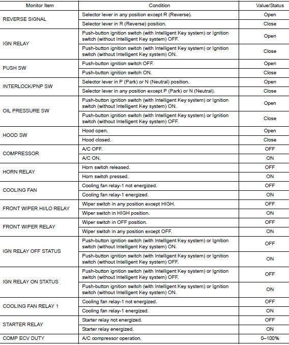
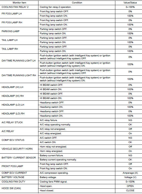
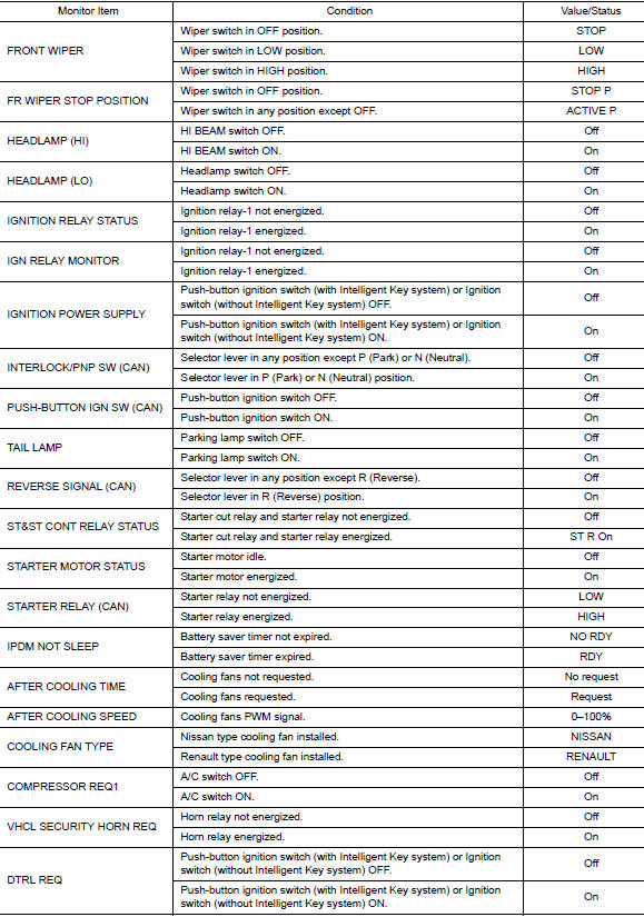
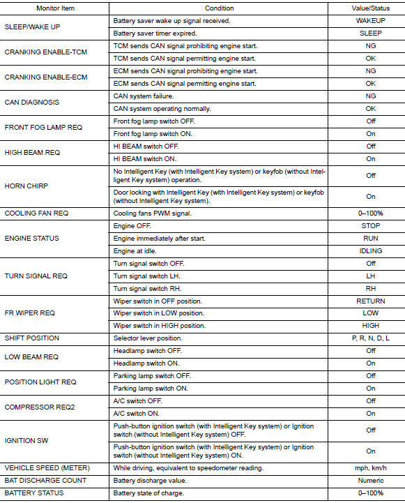
VALUES ON THE DIAGNOSIS TOOL
TERMINAL LAYOUT
PHYSICAL VALUES
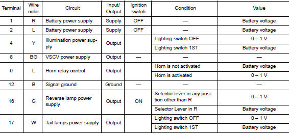
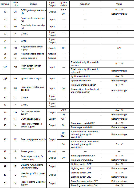
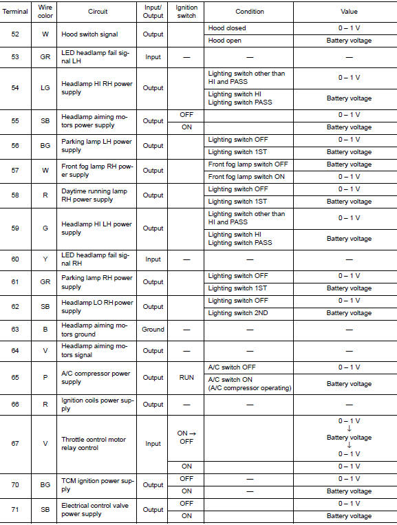
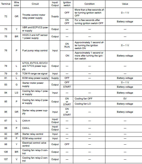
1: With Intelligent Key system
2: With remote keyless entry
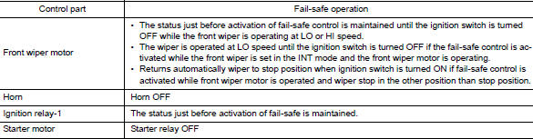
Fail-safe
CAN COMMUNICATION CONTROL
When CAN communication with ECM and BCM is impossible, IPDM E/R performs fail-safe control. After CAN communication recovers normally, it also returns to normal control.
If No CAN Communication Is Available With ECM

If No CAN Communication Is Available With BCM
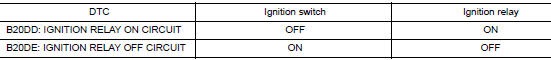
IGNITION RELAY MALFUNCTION DETECTION FUNCTION
- IPDM E/R monitors the voltage at the contact circuit and excitation coil circuit of the ignition relay-1 inside it.
- IPDM E/R judges the ignition relay-1 error if the voltage differs between the contact circuit and the excitation coil circuit.
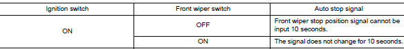
FRONT WIPER CONTROL
IPDM E/R detects front wiper stop position by a front wiper auto stop signal.
When a front wiper auto stop signal is in the conditions listed below, IPDM E/R stops power supply to wiper after repeating a front wiper 10 second activation and 20 second stop five times.
NOTE: This operation status can be confirmed on the IPDM E/R “Data Monitor” that displays “BLOCK” for the item “WIP PROT” while the wiper is stopped.
STARTER MOTOR PROTECTION FUNCTION
IPDM E/R turns OFF the starter relay to protect the starter motor when the starter relay remains active for 90 seconds.
DTC Index
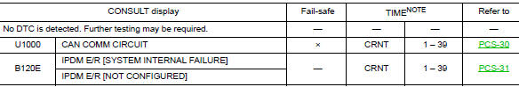
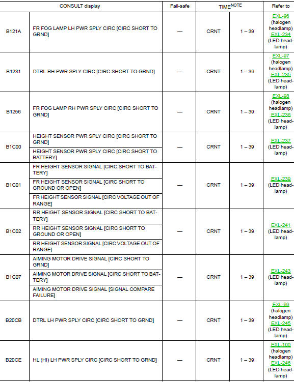
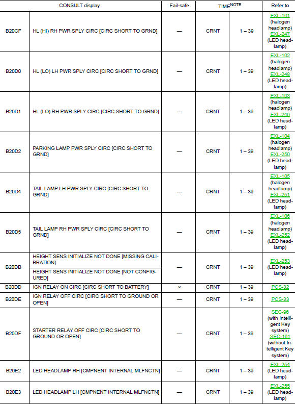
NOTE: The details of TIME display are as follows.
- CRNT: The malfunctions that are detected now
- 1 - 39: The number is indicated when it is normal at present and a malfunction was detected in the past. It increases like 0 → 1 → 2 ··· 38 → 39 after returning to the normal condition whenever IGN OFF → ON. It is fixed to 39 until the self-diagnosis results are erased if it is over 39. It returns to 0 when a malfunction is detected again in the process.
 System description
COMPONENT PARTS
Component Parts Location
IPDM E/R
Engine compartment (LH)
SYSTEM
RELAY CONTROL SYSTEM
RELAY CONTROL SYSTEM : System Description
SYSTEM DIAGRAM
DESCRIPTION
...
 Wiring diagram
IPDM E/R (INTELLIGENT POWER DISTRIBUTION MODULE ENGINE
ROOM)
Wiring Diagram
...
Other materials:
Front wiper motor ground circuit
Diagnosis Procedure
Regarding Wiring Diagram information, refer to WW-22, "Wiring Diagram".
1. CHECK FRONT WIPER MOTOR GROUND CIRCUIT
Turn the ignition switch OFF.
Disconnect front wiper motor.
Check continuity between front wiper motor harness connector and
...
Unit disassembly and assembly
COMBINATION METER
Exploded View
Combination meter
Combination meter lens
Pawl
Disassembly and Assembly
CAUTION:
Do not touch the display, pointer, inside of combination meter
or the printed area of the dial during
disassembly or assembly.
Keep away from magn ...
P0967 pressure control solenoid B
DTC Description
DTC DETECTION LOGIC
DTC
CONSULT screen terms
(Trouble diagnosis content)
DTC detection condition
P0967
PC SOLENOID B
(Pressure Control Solenoid B Control Circuit
High)
When all of the following conditions are satisfied and this state is
main ...
