Nissan Rogue Owners Manual: Ignition switch (if so equipped)
WARNING
|
Continuously Variable Transmission (CVT)
Continuously Variable Transmission (CVT)
The ignition lock is designed so that the ignition switch cannot be turned to the LOCK position until the shift lever is moved to the P (Park) position.
- When moving the ignition switch to the LOCK position, make sure the shift lever is in the P (Park) position.
- When removing the key from the ignition switch, make sure the shift lever is in the P (Park) position.
When the ignition switch cannot be turned to the LOCK position:
- Shift the shift lever to the P (Park) position.
- Turn the ignition switch slightly in the ON direction.
- Turn the ignition switch to the LOCK position.
- Remove the key if it is inserted in the ignition switch.
If the ignition switch is turned to the LOCK position, the shift lever cannot be moved from the P (Park) position.
The shift lever can be moved if the ignition switch is placed in the ON position and the foot brake pedal is depressed.
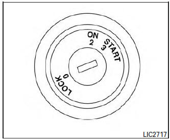
Key positions
LOCK: Normal parking position (0)
OFF: (Not used) (1)
This position activates electrical accessories such as the radio when the engine is not running.
ON: Normal operating position (3)
This position turns on the ignition system and the electrical accessories.
START: (4)
This position starts the engine. As soon as the engine has started, release the key. It automatically returns to the ON position.
NISSAN vehicle immobilizer system
The NISSAN Vehicle Immobilizer system will not allow the engine to start without the use of the registered key.
If the engine fails to start using a registered key (for example, when interference is caused by another registered key, an automated toll road device or automatic payment device on the key ring), restart the engine using the following procedure:
- Leave the ignition switch in the ON position for approximately 5 seconds.
- Place the ignition switch in the OFF or LOCK position, and wait approximately 10 seconds.
- Repeat Steps 1 and 2.
- Restart the engine while holding the device (which may have caused the interference) separate from the registered key.
If the no start condition re-occurs, NISSAN recommends placing the registered key on a separate key ring to avoid interference from other devices.
 Driving safety precautions
Your NISSAN is designed for both normal and
off-road use. However, avoid driving in deep water
or mud as your NISSAN is mainly designed for
leisure use, unlike a conventional off-road vehicle.
R ...
 Push-Button Ignition Switch (if so equipped)
WARNINGDo not operate the push-button ignition
switch while driving the vehicle except in
an emergency. (The engine will stop when
the ignition switch is pushed 3 consecutive
times ...
Other materials:
Unbalance steering wheel turning force and return between
right and left
Description
Unbalance steering wheel turning force and return between right and left.
Diagnosis Procedure
1.CHECK THE ILLUMINATION OF THE EPS WARNING LAMP
Check the EPS warning lamp while engine is running.
Does the EPS warning lamp turn OFF?
YES >> GO TO 2.
NO >> Refer to STC ...
Overdrive control switch
Component Function Check
1.CHECK O/D OFF INDICATOR LAMP FUNCTION
Check O/D OFF indicator lamp turns ON for approx. 2 seconds when ignition
switch turns ON.
Is the inspection results normal?
YES >> GO TO 2.
NO >> Go to TM-181, "Diagnosis Procedure".
2.CHECK OVERDRIVE ...
Oil
Description
MAINTENANCE OF OIL LEVEL
The compressor oil is circulating in the system together with the
refrigerant. It is necessary to fill compressor
with oil when replacing A/C system parts or when a large amount of refrigerant
leak is detected. It is important
to always maintain oil level ...
