Nissan Rogue Owners Manual: Installing front license plate
Installing front license plate
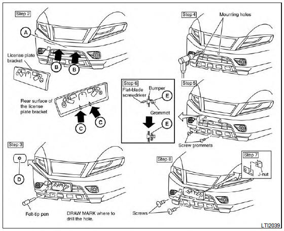
Use the following steps to mount the front license plate:
Before mounting the license plate, confirm that the following parts are enclosed in the plastic bag:
- License plate bracket
- License plate bracket (J-nut) screws x 2
- License plate screws x 2
- Screw grommets x 2
- Park the vehicle on flat, level ground.
- Locate the center position A as illustrated.
Line up the license plate bracket under the top of the front bumper B with the tabs C .
Hold the license plate bracket in place.
- Mark the center of the hole D with a felt-tip pen.
- Carefully drill two pilot holes using a 0.39 in (10 mm) drill bit at the marked locations. (Be sure that the drill only goes through the bumper fascia.)
- Insert the grommets into the holes in the bumper fascia.
- Insert a small flat-bladed screwdriver into the grommet hole to turn the threaded part of the grommet 90° E .
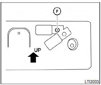
Mark the center of the hole F on both sides with a felt-tip pen. Remove the bracket from the bumper, and then open 0.79 in (20 mm) diameter holes on the bumper using the marks F as a center.
- Insert a J-nut into the license plate bracket before placing the license plate bracket on the fascia.
- Install the license plate bracket with screws.
- Install the license plate with bolts that are no longer than 0.55 in (14 mm).
 Vehicle identification
Vehicle identification number (VIN) plate
The vehicle identification number (VIN) plate is
located as shown. This number is the identification
for your vehicle and is used in the vehicle
regi ...
 Vehicle loading information
WARNING
It is extremely dangerous to ride
in a cargo area inside a vehicle. In
a collision, people riding in these
areas are more likely to be seriously
injured or kil ...
Other materials:
Securing the load
Cargo area luggage hooks
There are luggage hooks located in the cargo
area as shown. The hooks can be used to secure
cargo with ropes or other types of straps.
Do not apply a total load of more than
6.5 lbs. (29 N) to a single metal floor hook
when securing cargo.
WARNING
&nb ...
P0507 ISC system
Description
The ECM controls the engine idle speed to a specified level through the fine
adjustment of the air, which is let
into the intake manifold, by operating the electric throttle control actuator.
The operating of the throttle valve is
varied to allow for optimum control of the engine ...
Instrument panel
Vent
Headlight/fog light (if so equipped)/turn signal switch
Meters, gauges, warning/indicator
lights and Vehicle Information Display
Windshield wiper/washer switch and rear window wiper/washer switch
/Ignition switch (if so equipped)
Push-button ...
