Nissan Rogue (T33) 2021-Present Service Manual: Sunload Sensor
Diagnosis Procedure
CHECK SUNLOAD SENSOR SIGNAL
-
Ignition switch ON.
-
Check voltage between A/C amp. harness connector.
A/C amp. Voltage Connector Terminal (+) (â) M55 47 78 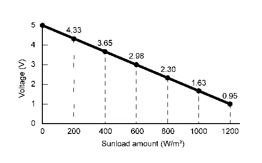
Is the inspection result normal?
YES>>Inspection End.
NO>>GO TO 2.
CHECK SUNLOAD SENSOR POWER SUPPLY
-
Ignition switch OFF.
-
Disconnect sunload sensor connector.
-
Ignition switch ON.
-
Check voltage between sunload sensor harness connector and ground.
(+) (â) Voltage
(Approx.)Sunload sensor Connector Terminal M64 1 Ground 5 V
Is the inspection result normal?
YES>>GO TO 3.
NO>>GO TO 5.
CHECK SUNLOAD SENSOR GROUND CIRCUIT FOR OPEN
-
Ignition switch OFF.
-
Disconnect A/C amp. connector.
-
Check continuity between sunload sensor harness connector and A/C amp. harness connector.
Sunload sensor A/C amp. Continuity Connector Terminal Connector Terminal M64 2 M55 78 Yes
Is the inspection result normal?
YES>>GO TO 4.
NO>>Repair harness or connector.
REPLACE SUNLOAD SENSOR
Replace sunload sensor. Refer to Removal and Installation.
Is the inspection result normal?
YES>>Inspection End.
NO>>Replace A/C amp. Refer to Removal and Installation.
CHECK SUNLOAD SENSOR POWER SUPPLY CIRCUIT FOR OPEN
-
Ignition switch OFF.
-
Disconnect A/C amp. connector.
-
Check continuity between sunload sensor harness connector and A/C amp. harness connector.
Sunload sensor A/C amp. Continuity Connector Terminal Connector Terminal M64 1 M55 47 Yes
Is the inspection result normal?
YES>>GO TO 6.
NO>>Repair harness or connector.
CHECK SUNLOAD SENSOR POWER SUPPLY CIRCUIT FOR SHORT
Check continuity between sunload sensor harness connector and ground.
| Sunload sensor | (â) | Continuity | |
|---|---|---|---|
| Connector | Terminal | ||
| M64 | 1 | Ground | No |
Is the inspection result normal?
YES>>GO TO 4.
NO>>Repair harness or connector.
Other materials:
Operating manual liftgate
To open the liftgate of your Nissan Rogue, unlock it and pull upward to raise the door.
The liftgate can be unlocked by:
pushing the UNLOCK
button on the Intelligent Key twice.
pushing the liftgate request switch (if equipped).
pushing the door handle request switch (if equipped).
To clo ...
Protection contre la corrosion
Facteurs de corrosion les plus courants
Accumulation de poussiÃĻre humide, de sable et de dÃĐbris dans les panneaux de carrosserie, les orifices et les zones peu ventilÃĐes.
Dommages de la peinture ou des revÊtements protecteurs causÃĐs par des projections de gravillons ou de petits accidents ...
C10b0-09 Parking Brake Actuator (rh)
DTC Description
DTC DETECTION LOGIC DTC No.
CONSULT screen terms
(Trouble diagnosis content) DTC detection condition
C10B0
09
Parking brake actuator (RH)
[Parking brake actuator (right)]
Diagnosis condition
When parking brake is apply
Signal (terminal)
â
Threshol ...