Nissan Rogue (T33) 2021-Present Service Manual: Door Motor
Diagnosis Procedure
 NOTE:
NOTE:
If all of door motor DTCs are detected, check this circuit.
CHECK DOOR MOTOR POWER SUPPLY
-
Ignition switch ON.
-
Check voltage between intake door motor harness connector and A/C amp. harness connector.
| (+) | (ŌłÆ) | Voltage | ||
|---|---|---|---|---|
| Intake door motor | A/C amp. | |||
| Connector | Terminal | Connector | Terminal | |
| M147 | 1 | M55 | 58 | Battery voltage |
Is the inspection result normal?
YES>>GO TO 2.
NO>>GO TO 6.
CHECK DOOR MOTOR GROUND CIRCUIT FOR OPEN
-
Ignition switch OFF.
-
Disconnect intake door motor connector and A/C amp. connector.
-
Check continuity between intake door motor harness connector and A/C amp. harness connector.
Intake door motor A/C amp. Continuity Connector Terminal Connector Terminal M147 2 M54 27 Yes
Is the inspection result normal?
YES>>GO TO 3.
NO>>Repair harness or connector.
CHECK DOOR MOTOR LIN SIGNAL
-
Connect intake door motor connector and A/C amp. connector.
-
Ignition switch ON.
-
Confirm output waveform between intake door motor harness connector and A/C amp. harness connector with oscilloscope.
(+) (ŌłÆ) Output waveform Intake door motor A/C amp. Connector Terminal Connector Terminal M147 3 M55 58 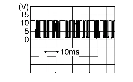
Is the inspection result normal?
YES>>Inspection End.
NO>>GO TO 4.
CHECK DOOR MOTOR LIN SIGNAL CIRCUIT FOR OPEN
-
Ignition switch OFF.
-
Disconnect A/C amp. and intake door motor connector.
-
Check continuity between intake door motor harness connector and A/C amp. harness connector.
Intake door motor A/C amp. Continuity Connector Terminal Connector Terminal M147 1 M54 1 Yes
Is the inspection result normal?
YES>>GO TO 5.
NO>>Repair harness or connector.
CHECK DOOR MOTOR LIN SIGNAL CIRCUIT FOR SHORT
-
Ignition switch OFF.
-
Disconnect following connectors.
-
Air mix door motor LH
-
Air mix door motor RH
-
Air mix door motor (rear)
-
Mode door motor
-
-
Check continuity between A/C amp. harness connector and ground.
A/C amp. (ŌĆö) Continuity Connector Terminal M54 2 Ground No
Is the inspection result normal?
YES>>Replace A/C amp. Refer to Removal and Installation.
NO>>Repair harness or connector.
CHECK DOOR MOTOR POWER SUPPLY CIRCUIT FOR OPEN
-
Ignition switch OFF.
-
Disconnect intake door motor and A/C amp. connector.
-
Check continuity between intake door motor harness connector and A/C amp. harness connector.
Intake door motor A/C amp. Continuity Connector Terminal Connector Terminal M147 1 M54 1 Yes
Is the inspection result normal?
YES>>GO TO 7.
NO>>Repair harness or connector.
CHECK DOOR MOTOR POWER SUPPLY CIRCUIT FOR SHORT
-
Disconnect following connectors.
-
Air mix door motor LH
-
Air mix door motor RH
-
Air mix door motor (rear)
-
Mode door motor
-
-
Check continuity between A/C amp. harness connector and ground.
A/C amp. (ŌĆö) Continuity Connector Terminal M54 1 Ground No
Is the inspection result normal?
YES>>Replace A/C amp. Refer to Removal and Installation.
NO>>Repair harness or connector.
Other materials:
P0335 Ckp Sensor 1
DTC Description
DTC DETECTION LOGIC DTC
CONSULT screen terms
(Trouble diagnosis content)
DTC detection condition
P0335
00
CKP SEN/CIRCUIT
(Crankshaft position sensor ŌĆ£AŌĆØ circuit)
Diagnosis condition
Engine running or cranking
Signal (terminal)
Crankshaft posit ...
Dtc/circuit Diagnosis. U2a06-88 Comm Bus Off V-Fd
DTC Description
DESCRIPTIONCAN (Controller Area Network) is a serial
communication line for real time applications. It is an on-Nissan Ariya
vehicle multiplex communication line with high data communication speed
and excellent error detection ability. Modern Nissan Ariya vehicle is
equipped ...
Dtc/circuit Diagnosis. Lin Communication Circuit
Diagnosis Procedure
CHECK BCM OUTPUT SIGNAL
Ignition switch ON.
Check signal between BCM harness connector and ground using an oscilloscope.
(+) (ŌłÆ)
Signal
(Reference value)
BCM
Connector Terminal
With type A meter: B123
91
Ground
With type B meter: M18 ...