Nissan Rogue (T33) 2021-Present Service Manual: P0335 Ckp Sensor 1
DTC Description
DTC DETECTION LOGIC
| DTC |
CONSULT screen terms (Trouble diagnosis content) |
DTC detection condition | ||
| P0335 | 00 |
CKP SEN/CIRCUIT (Crankshaft position sensor ŌĆ£AŌĆØ circuit) |
Diagnosis condition | Engine running or cranking |
| Signal (terminal) | Crankshaft position sensor (POS) signal | |||
| Threshold |
|
|||
| Diagnosis delay time | ŌĆö | |||
POSSIBLE CAUSE
-
Harness or connectors [Crankshaft position sensor (POS) circuit is open or shorted.]
-
Crankshaft position sensor (POS)
-
Signal plate
FAIL-SAFE
Engine Control System
| Fail safe mode | Nissan Ariya Vehicle behavior | |
|---|---|---|
| Device fix mode |
|
|
| Combustion control mode | Idle speed control | Stops feedback control of idle speed and controls with specified speed. |
| Recovery speed control at decelerating | Stops recovery speed control by the fuel cut at decelerating and controls with specified speed. | |
| Idle neutral control | Stops idle neutral control. | |
or
| Fail safe mode | Nissan Ariya Vehicle behavior | |
|---|---|---|
| Device fix mode |
|
|
| Combustion control mode | Stratified charge combustion control at starting | No stratified charge combustion at starting (cold start). |
or
| Fail safe mode | Nissan Ariya Vehicle behavior | |
|---|---|---|
| Device fix mode |
|
|
Stop/Start System
When a DTC is detected, the stop/start indicator lamp blinks slowly and the stop/start system operation is prohibited. When ECM detects error while operating the stop/start system, ECM restarts the engine.
DTC Confirmation Procedure
PRECONDITIONING
If DTC Confirmation Procedure has been previously conducted, always turn ignition switch OFF and wait at least 10 seconds before conducting the next test.
TESTING CONDITION:
Before performing the following procedure, confirm that battery voltage is more than 10.5 V with ignition switch ON.
>>
GO TO 2.
PERFORM DTC CONFIRMATION PROCEDURE
-
Start engine and let it idle for at least 5 seconds.
If engine does not start, crank engine for at least 2 seconds.
-
Check 1st trip DTC.
Is 1st trip DTC detected?
YES>>Proceed to DTC Diagnosis Procedure.
NO-1>>To check malfunction symptom before repair: Refer to Intermittent Incident.
NO-2>>Confirmation after repair: INSPECTION END
DTC Diagnosis Procedure
CHECK HARNESS CONNECTOR
-
Turn ignition switch OFF.
-
Disconnect crankshaft position (CKP) sensor harness connectors.
-
Reconnect crankshaft position (CKP) sensor harness connectors.
-
Perform DTC confirmation procedure.
Is DTC detected?
YES>>GO TO 2.
NO>>INSPECTION END
CHECK GROUND CONNECTION
Check ground connection.
Is the in spection result normal?
YES>>GO TO 3.
NO>>Repair or replace ground connection.
CHECK CRANKSHAFT POSITION (CKP) SENSOR POWER SUPPLY
-
Turn ignition switch OFF.
-
Disconnect crankshaft position (CKP) sensor (POS) harness connector.
-
Turn ignition switch ON.
-
Check the voltage between CKP sensor (POS) harness connector and ground.
CKP sensor (POS) Condition Voltage
(Approx.)Connector + ŌłÆ Terminal F17 1 2 Ignition switch: ON 5 V Ignition switch: OFF 0 V
Is the inspection result normal?
YES>>GO TO 8.
NO>>GO TO 4.
CHECK CKP SENSOR (POS) POWER SUPPLY CIRCUIT-2
-
Turn ignition switch OFF.
-
Disconnect ECM harness connector.
-
Check the continuity between CKP sensor (POS) harness connector and ECM harness connector.
| CKP sensor (POS) | ECM | Continuity | ||
|---|---|---|---|---|
| Connector | Terminal | Connector | Terminal | |
| F17 | 1 | F71 | 78 | Existed |
Is the inspection result normal?
YES>>GO TO 5.
NO>>Repair or replace malfunctioning part.
CHECK CKP SENSOR GROUND CIRCUIT
-
Turn ignition switch OFF.
-
Disconnect ECM harness connector.
-
Check the continuity between CKP sensor harness connector and ECM harness connector.
+ ŌłÆ Continuity CKP sensor ECM Connector Terminal Connector Terminal F17 2 F71 108 Existed
Is the inspection result normal?
YES>>GO TO 6.
NO>>Repair or replace error-detected parts.
CHECK ECM GROUND CIRCUIT
-
Check the continuity between ECM harness connector and ground.
ECM ŌĆö Continuity Connector Terminal F72 4 Ground Existed E21 156 157 160 -
Also check harness for short to power.
Is the inspection result normal?
YES>>GO TO 7.
NO>>Repair or replace malfunctioning part.
CHECK CKP SENSOR (POS) POWER SUPPLY CIRCUIT-3
-
Check the continuity between CKP sensor harness connector and ECM harness connector.
+ ŌłÆ Continuity CKP sensor ECM Connector Terminal Connector Terminal F17 3 F71 96 Existed -
Also check harness for short to ground and to power.
Is the inspection result normal?
YES>>GO TO 8.
NO>>Repair or replace error-detected parts.
CHECK CKP SENSOR (POS)
Check the crankshaft position sensor. Refer to Component Inspection.
Is the inspection result normal?
YES>>GO TO 9.
NO>>Replace crankshaft position sensor (POS). Refer to Exploded View.
CHECK GEAR TOOTH
-
Remove crankshaft position sensor. Refer to Exploded View.
-
Look into the mounting hole
 of the crankshaft position sensor to check that there is no missing gear tooth in the signal plate
 .
.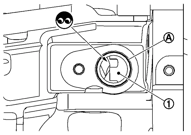
Is the inspection result normal?
YES>>INSPECTION END
NO>>Replace the signal plate. Refer to Exploded View.
Other materials:
P0261 Fuel Injector (cylinder 1)
DTC Description
DTC DETECTION LOGIC DTC
CONSULT screen terms
(Trouble diagnosis content)
DTC detection condition
P0261
00
CYL1 INJECTOR
(Cylinder 1 Injector A Circuit Low)
Diagnosis condition
ŌĆö
Signal (terminal)
ŌĆö
Threshold
Direct injector driver unit ...
Adas Control Unit. Basic Inspection
Additional Service When Replacing Adas Control Unit 2
Without Propilot Assist 2.1
Work Procedure
Always perform the additional service after replacing the ADAS control unit 2.ADAS CONTROL UNIT 2 CONFIGURATION
Perform saving Nissan Ariya vehicle internal information according to "Replace ECU" i ...
P00fe Evap Control System
DTC Description
This diagnosis detects clogs in the EVAP line between fuel tank and EVAP canister purge volume control solenoid valve.ECM
controls EVAP control system as below. ECM monitors EVAP line pressure
change to diagnose if there is no clogging between EVAP canister and
fuel tank.
E ...