Nissan Rogue (T33) 2021-Present Service Manual: P0340 Intake Camshaft Position Sensor
DTC Description
DTC DETECTION LOGIC
| DTC |
CONSULT screen terms (Trouble diagnosis content) |
DTC detection condition | ||
| P0340 | 00 |
CMP SEN/CIRC-B1 (Camshaft position sensor ŌĆ£AŌĆØ circuit bank 1 or single sensor) |
Diagnosis condition | Engine: Cranking or running (idle speed or more than 800 rpm) |
| Signal (terminal) | Intake camshaft position sensor signal | |||
| Threshold |
|
|||
| Diagnosis delay time | ŌĆö | |||
POSSIBLE CAUSE
-
Harness or connectors
-
The intake camshaft position sensor circuit is open or shorted.
-
Sensor power supply 2 circuit is shorted.
-
-
Intake camshaft position sensor
-
Exhaust camshaft position sensor
-
Camshaft (INT)
-
Starter motor
-
Starting system circuit
-
Dead (Weak) battery
-
Sensor power supply 2 circuit sensor
FAIL-SAFE
Engine Control System
| Fail safe mode | Nissan Ariya Vehicle behavior | |
|---|---|---|
| Device fix mode |
|
|
| Combustion control mode | Idle speed control | Stops feedback control of idle speed and controls with specified speed. |
| Recovery speed control at decelerating | Stops recovery speed control by the fuel cut at decelerating and controls with specified speed. | |
| Idle neutral control | Stops idle neutral control. | |
or
| Fail safe mode | Nissan Ariya Vehicle behavior | |
|---|---|---|
| Device fix mode |
|
|
| Combustion control mode | Stratified charge combustion control at starting | No stratified charge combustion at starting (cold start). |
or
| Fail safe mode | Nissan Ariya Vehicle behavior | |
|---|---|---|
| Device fix mode |
|
|
Stop/Start System
When a DTC is detected, the stop/start indicator lamp blinks slowly and the stop/start system operation is prohibited. When ECM detects error while operating the stop/start system, ECM restarts the engine.
DTC Confirmation Procedure
CHECK DTC PRIORITY
If DTCP0340 is displayed with DTC P06B0 or P06B3, first perform the trouble diagnosis for DTC P06B0 or P06B3.
Is applicable DTC detected?
YES>>Perform diagnosis of applicable. Refer to DTC Description.
NO>>GO TO 2.
PRECONDITIONING
If DTC Confirmation Procedure has been previously conducted, always turn ignition switch OFF and wait at least 10 seconds before conducting the next test.
TESTING CONDITION:
Before performing the following procedure, confirm that battery voltage is more than 10.5 V with ignition switch ON.
>>
GO TO 3.
PERFORM DTC CONFIRMATION PROCEDURE-1
-
Start engine and let it idle for at least 5 seconds.
If engine does not start, crank engine for at least 2 seconds.
-
Check 1st trip DTC.
Is 1st trip DTC detected?
YES>>Proceed to DTC Diagnosis Procedure
NO>>GO TO 4.
PERFORM DTC CONFIRMATION PROCEDURE-2
-
Maintaining engine speed at more than 800 rpm for at least 5 seconds.
-
Check 1st trip DTC.
Is 1st trip DTC detected?
YES>>Proceed to DTC Diagnosis Procedure.
NO-1>>To check malfunction symptom before repair: Refer to Intermittent Incident.
NO-2>>Confirmation after repair: INSPECTION END
DTC Diagnosis Procedure
CHECK DTC PRIORITY
If DTCP0340 is displayed with DTC P06B0 or P06B3, first perform the trouble diagnosis for DTC P06B0 or P06B3.
Is applicable DTC detected?
YES>>Perform diagnosis of applicable. Refer to DTC Description.
NO>>GO TO 2.
CHECK STARTING SYSTEM
Turn ignition switch to START position.
Does the engine turn over? Does the starter motor operate?
YES>>GO TO 3.
NO>>Check starting system. Refer to Work Flow.
CHECK INTAKE CAMSHAFT POSITION (CMP) SENSOR POWER SUPPLY
-
Turn ignition switch OFF.
-
Disconnect intake camshaft position (CMP) sensor (PHASE) harness connector.
-
Turn ignition switch ON.
-
Check the voltage between intake CMP sensor (PHASE) harness connector terminals.
Intake CMP sensor (PHASE) Voltage
(Approx.)Connector + ŌłÆ Terminal F102 1 2 5 V
Is the inspection result normal?
YES>>GO TO 8.
NO>>GO TO 4.
CHECK INTAKE CMP SENSOR (PHASE) POWER SUPPLY-2
Check the voltage between intake CMP sensor (PHASE) harness connector and ground.
| + | ŌłÆ |
Voltage (Approx.) | |
|---|---|---|---|
| Intake CMP sensor | |||
| Connector | Terminal | ||
| F102 | 1 | Ground | 5 V |
Is the inspection result normal?
YES>>GO TO 6.
NO>>GO TO 5.
CHECK INTAKE CMP SENSOR (PHASE) POWER SUPPLY CIRCUIT
-
Turn ignition switch OFF.
-
Disconnect ECM harness connector.
-
Check the continuity between intake CMP sensor (PHASE) harness connector and ECM harness connector.
Intake CMP sensor (PHASE) ECM Continuity Connector Terminal Connector Terminal F102 1 F71 86 Existed
Is the inspection result normal?
YES>>GO TO 6.
NO>>Repair or replace malfunctioning part.
CHECK INTAKE CMP SENSOR (PHASE) GROUND CIRCUIT
-
Turn ignition switch OFF.
-
Disconnect ECM harness connector.
-
Check the continuity between intake CMP sensor (PHASE) harness connector and ECM harness connector.
+ ŌłÆ Continuity Intake CMP sensor ECM Connector Terminal Connector Terminal F102 2 F71 100 Existed -
Also check harness for short to power.
Is the inspection result normal?
YES>>GO TO 7.
NO>>Repair or replace error-detected parts.
CHECK ECM GROUND CIRCUIT
-
Check the continuity between ECM harness connector and ground.
ECM ŌĆö Continuity Connector Terminal F72 4 Ground Existed E21 156 157 160 -
Also check harness for short to power.
Is the inspection result normal?
YES>>INSPECTION END
NO>>Repair or replace malfunctioning part.
CHECK INTAKE CMP SENSOR (PHASE) INPUT SIGNAL CIRCUIT
-
Check the continuity between intake CMP sensor harness connector and ECM harness connector.
+ ŌłÆ Continuity Intake CMP sensor ECM Connector Terminal Connector Terminal F102 3 F71 109 Existed -
Also check harness for short to ground and to power.
Is the inspection result normal?
YES>>GO TO 9.
NO>>Repair or replace malfunctioning part.
CHECK INTAKE CAMSHAFT POSITION SENSOR (PHASE)
Refer to Component Inspection.
Is the inspection result normal?
YES>>GO TO 10.
NO>>Replace intake camshaft position sensor (PHASE). Refer to Removal and Installation.
CHECK CAMSHAFT (INT)
Check the following.
-
Accumulation of debris to the signal plate of camshaft
 rear end
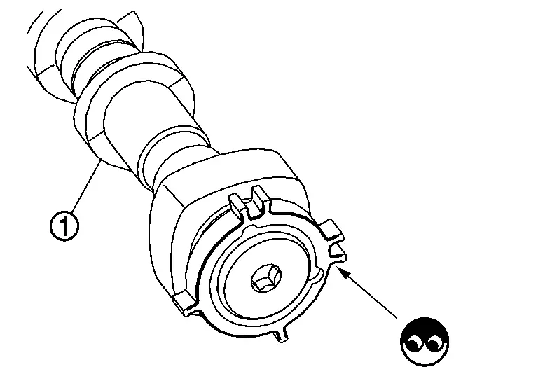
-
Chipping signal plate of camshaft rear end
Is the inspection result normal?
YES>>INSPECTION END
NO>>Remove debris and clean the signal plate of camshaft rear end or replace camshaft. Refer to Removal and Installation.
Other materials:
Symptom Diagnosis. Ignition Position Warning Function Does Not Operate
Diagnosis Procedure
CHECK POWER DOOR LOCK OPERATION
Check door lock/unlock using door lock/unlock switch.
Does door lock/unlock with door lock/unlock switch?
YES>>
GO TO 2.
NO>>
Refer to Diagnosis Procedure.
CHECK DOOR SWITCH
Check front door switch (front LH).
Refer to Compo ...
B2e08-01 Microphone
DTC Description
DTC DETECTION LOGIC DTC No.
CONSULT screen terms
(Trouble diagnosis content) DTC detection condition
B2E08ŌĆō01
Microphone
(Microphone)
1
Diagnosis condition
When ignition switch is ON.
Signal (terminal)
Microphone signal
Threshold
7.2 V or more ...
Dtc/circuit Diagnosis. Lin Communication Circuit
Diagnosis Procedure
CHECK BCM OUTPUT SIGNAL
Ignition switch ON.
Check signal between BCM harness connector and ground using an oscilloscope.
(+) (ŌłÆ)
Signal
(Reference value)
BCM
Connector Terminal
With type A meter: B123
91
Ground
With type B meter: M18 ...