Nissan Rogue (T33) 2021-Present Service Manual: Led Headlamp :: Removal and Installation
Headlamp
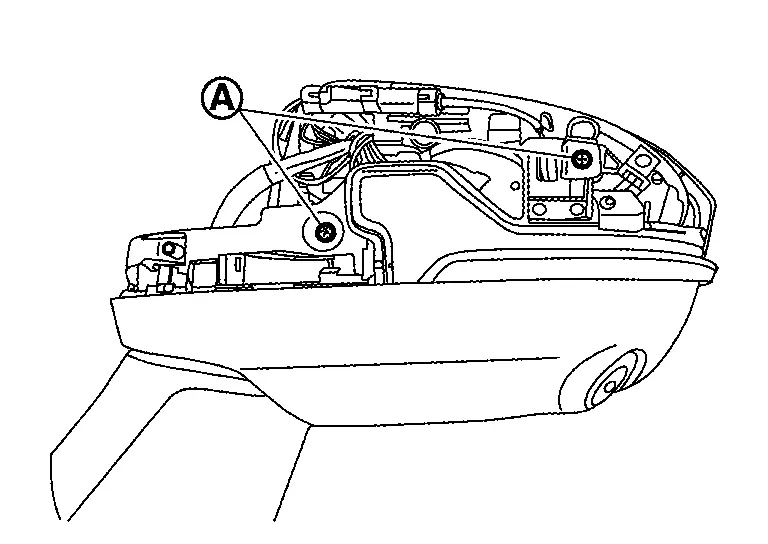
Exploded View
REMOVAL
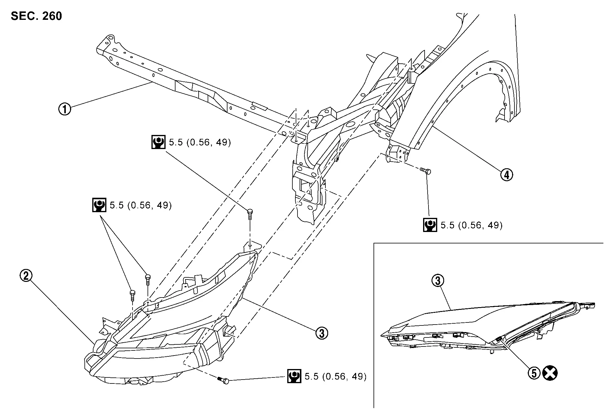
 |
Radiator core support |  |
Headlamp |  |
Front combination lamp |
 |
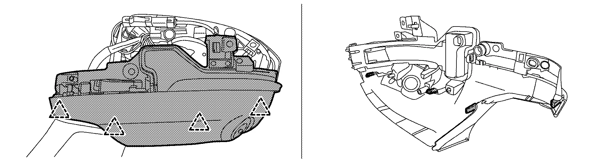
Front fender assembly |  |
Protector tape (USA production models) | ||
 |
: Always replace after every disassembly. | ||||
 |
: Nôñm (kg-m, in-lb) | ||||
DISASSEMBLY
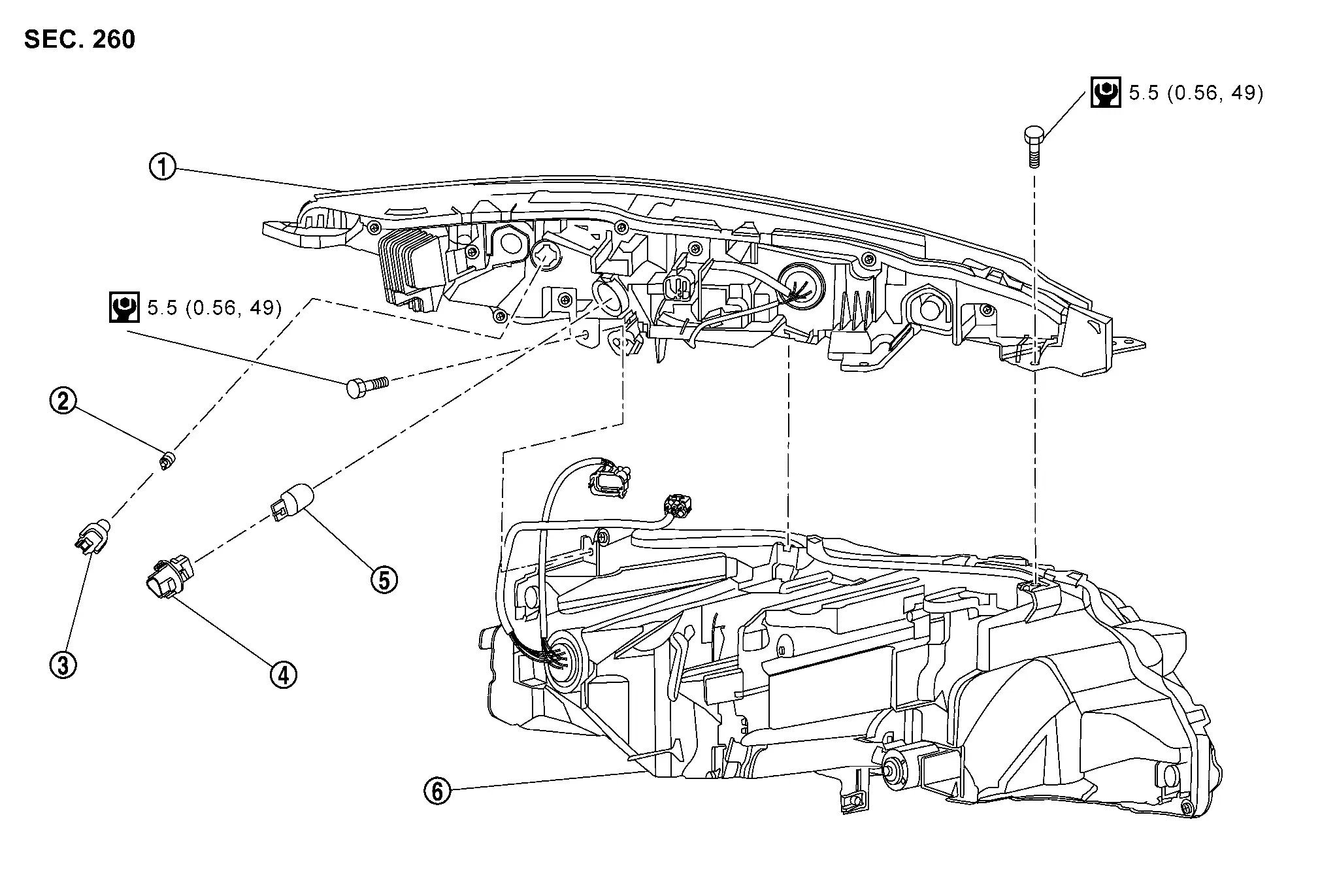
Front turn signal lamp (LED type)
|
Front combination lamp | |
Front side marker lamp bulb |  |
Front side marker lamp bulb socket |
|
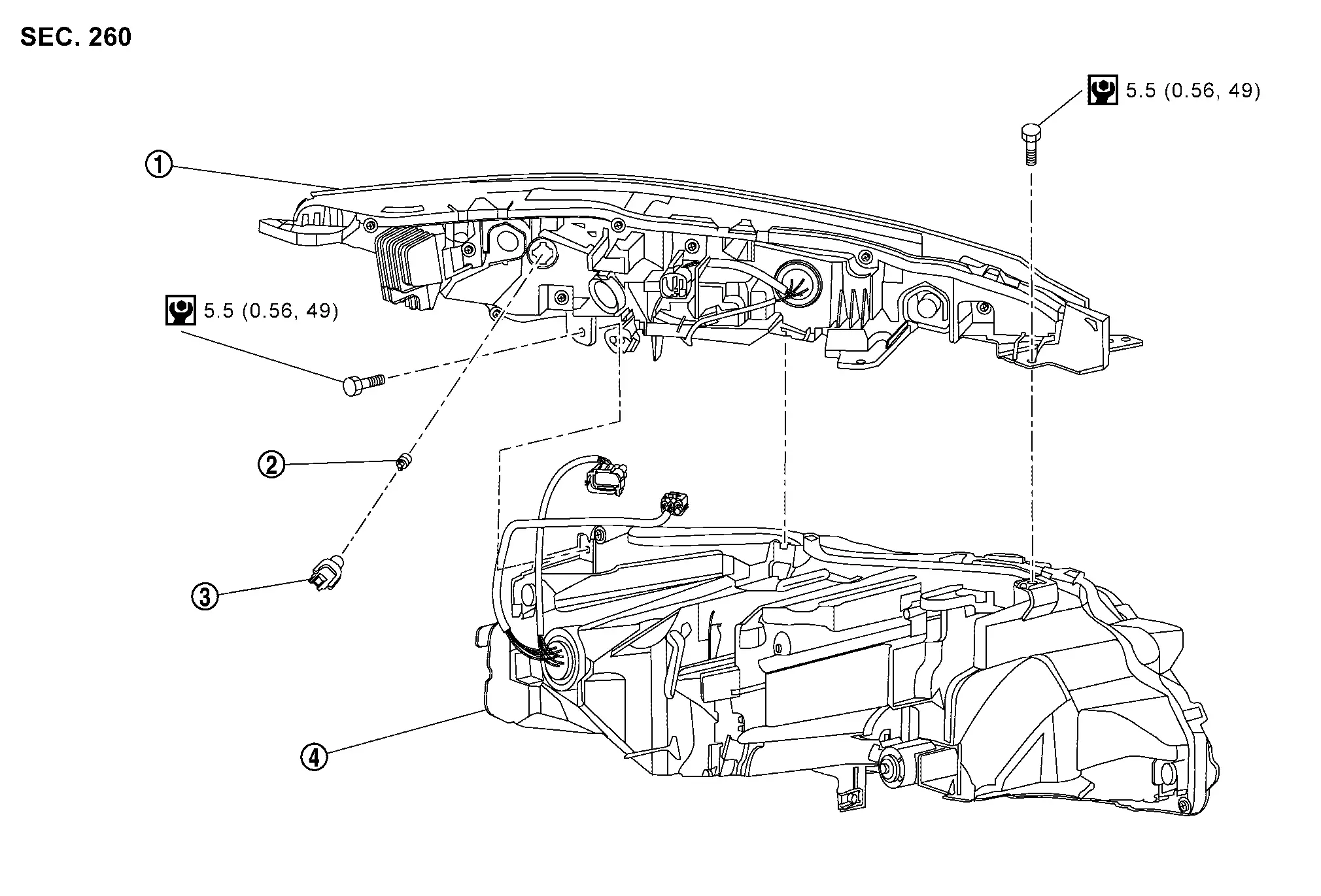
Headlamp | ||||
|
: Nôñm (kg-m, in-lb) | ||||
Front turn signal lamp (bulb type)
|
Front combination lamp | |
Front side marker lamp bulb | |
Front side marker lamp bulb socket |
|
Front turn signal lamp bulb socket | |
Front turn signal lamp bulb |  |
Headlamp |
|
: Nôñm (kg-m, in-lb) | ||||
Removal and Installation
CAUTION:
Disconnect the battery negative terminal or remove power circuit fuse when performing the operation for preventing electric leakage. Refer to Precautions for Removing Battery Terminal.
REMOVAL
Remove front bumper fascia. Refer to Removal and Installation.
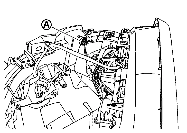
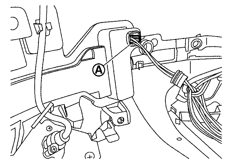
Disconnect headlamp and front combination lamp harness connectors.
Remove headlamp and front combination lamp mounting bolts.
Pull out headlamp and front combination lamp forward the Nissan Ariya vehicle.
Remove harness clip of headlamp rear side, and then remove headlamp and front combination lamp.
Disconnect headlamp harness connector from front combination lamp.
Remove headlamp and front combination lamp mounting bolts, and then remove headlamp.
INSTALLATION
Note the following item, and then install in the reverse order of removal.
CAUTION:
After installation, perform aiming adjustment. Refer to Adjustment.
Replacement
CAUTION:
Disconnect the battery negative terminal or remove power circuit fuse when performing the operation for preventing electric leakage. Refer to Precautions for Removing Battery Terminal.
HEADLAMP (Hi)
CAUTION:
Replacement of a single part is not possible due to the adoption of LED. For replacement, replace headlamp as a set. Refer to Removal and Installation.
HEADLAMP (Lo)
CAUTION:
Replacement of a single part is not possible due to the adoption of LED. For replacement, replace headlamp as a set. Refer to Removal and Installation.
Front Combination Lamp
Exploded View
For exploded view of front combination lamp. Refer to Exploded View.
Removal and Installation
CAUTION:
Disconnect the battery negative terminal or remove power circuit fuse when performing the operation for preventing electric leakage. Refer to Precautions for Removing Battery Terminal.
REMOVAL
Remove headlamp. Refer to Removal and Installation.
Remove front combination lamp.
INSTALLATION
Note the following item, and then install in the reverse order of removal.
CAUTION:
-
After installation, perform aiming adjustment. Refer to Adjustment.
-
When replace front combination lamp, put protector tape
on the position as shown. (USA production models)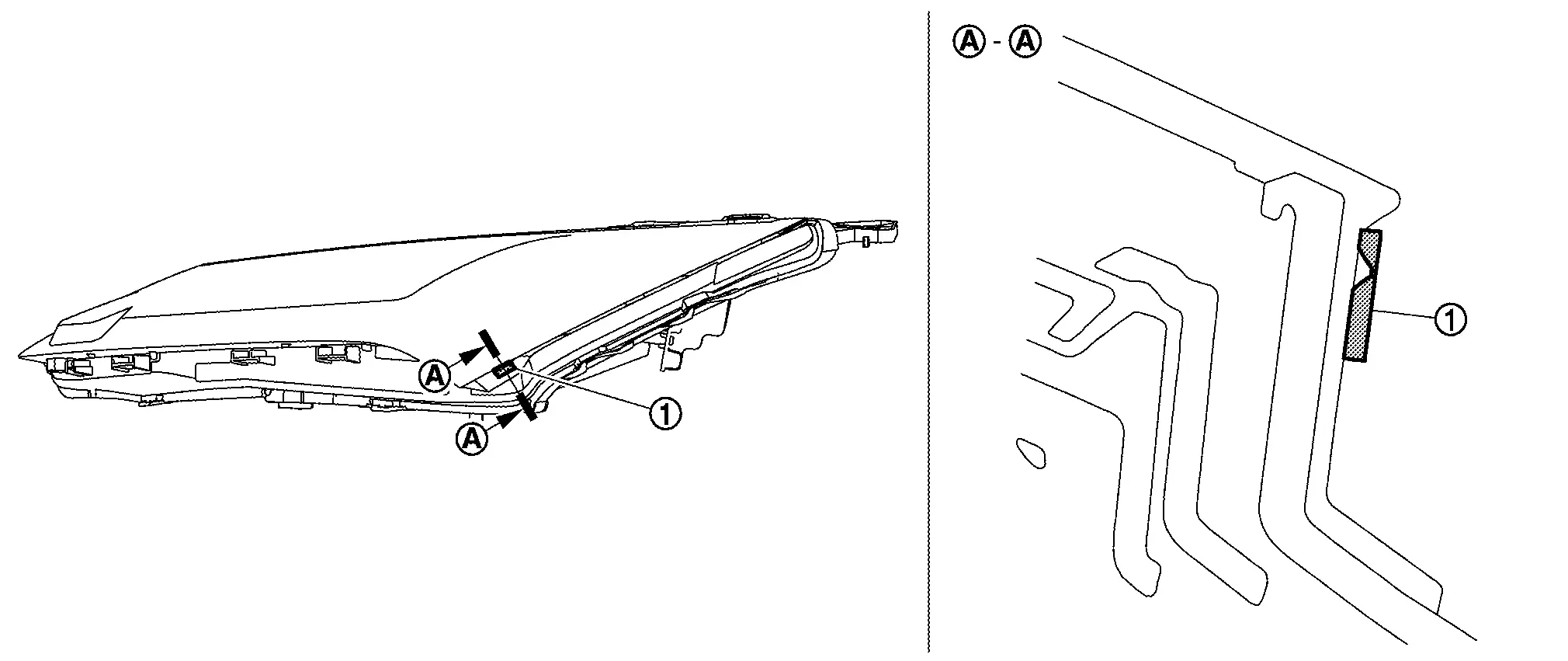
-
If the tape is visible after installing front combination lamp back, remove the tape and adjust until the tape is covered completely. (USA production models)
Replacement
CAUTION:
-
Disconnect the battery negative terminal or remove power circuit fuse when performing the operation for preventing electric leakage. Refer to Precautions for Removing Battery Terminal.
-
After installing the bulb, install the bulb socket securely for watertightness.
-
Never touch the glass of bulb directly by hand. Keep grease and other oily matters away from it.
-
Never touch bulb by hand while it is lit or right after being turned OFF.
-
Never leave bulb out of lamp reflector for a long time because dust, moisture smoke, etc. may affect the performance of lamp. When replacing bulb, be sure to replace it with new one.
PARKING LAMP
CAUTION:
Replacement of a single part is not possible due to the adoption of LED. For replacement, replace front combination lamp as a set. Refer to Removal and Installation.
DAYTIME RUNNING LIGHT
CAUTION:
Replacement of a single part is not possible due to the adoption of LED. For replacement, replace front combination lamp as a set. Refer to Removal and Installation.
FRONT TURN SIGNAL LAMP (LED TYPE)
CAUTION:
Replacement of a single part is not possible due to the adoption of LED. For replacement, replace front combination lamp as a set. Refer to Removal and Installation.
FRONT TURN SIGNAL LAMP (BULB TYPE)
Rotate front turn signal lamp bulb socket counterclockwise and unlock it.
Remove front turn signal lamp bulb from front turn signal lamp bulb socket.
FRONT SIDE MARKER LAMP
Rotate front side marker lamp bulb socket counterclockwise and unlock it.
Remove front side marker lamp bulb from front side marker lamp bulb socket.
Side Turn Signal Lamp
Exploded View
For exploded view of side turn signal lamp. Refer to Exploded View.
Removal and Installation
CAUTION:
Disconnect the battery negative terminal or remove power circuit fuse when performing the operation for preventing electric leakage. Refer to Precautions for Removing Battery Terminal.
REMOVAL
Remove door mirror cover. Refer to Removal and Installation.
Remove door mirror finisher fixing screws  .
.
Disengage door mirror finisher fixing pawls, and then remove door mirror finisher.
 |
: Pawl |
Remove cover cap .
Disconnect side turn signal lamp harness connector .
Remove side camera (with side camera). Refer to Removal and Installation.
Remove side turn signal lamp.
INSTALLATION
Install in the reverse order of removal.
Replacement
CAUTION:
Disconnect the battery negative terminal or remove power circuit fuse when performing the operation for preventing electric leakage. Refer to Precautions for Removing Battery Terminal.
SIDE TURN SIGNAL LAMP
CAUTION:
Replacement of a single part is not possible due to the adoption of LED. For replacement, replace side turn signal lamp as a set. Refer to Removal and Installation.
Optical Sensor
Exploded View
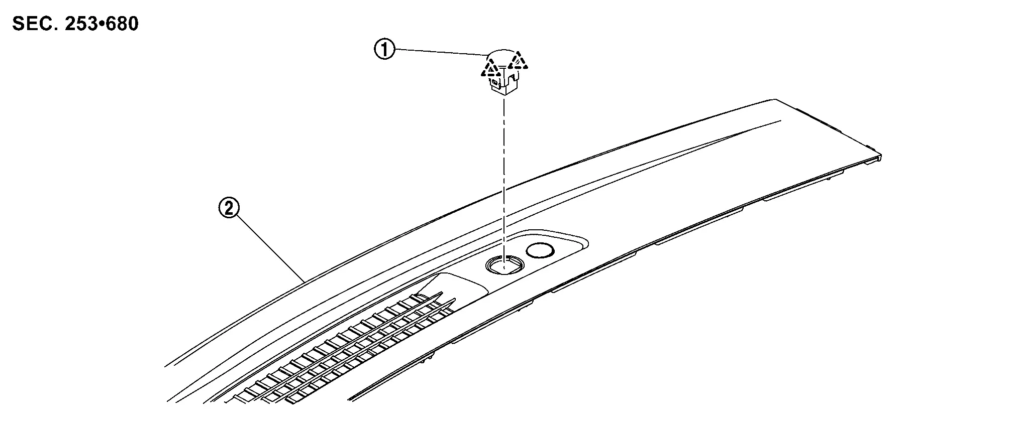
|
Optical sensor | |
Instrument garnish | ||
|
: Pawl | ||||
Removal and Installation
CAUTION:
Disconnect the battery negative terminal or remove power circuit fuse when performing the operation for preventing electric leakage. Refer to Precautions for Removing Battery Terminal.
REMOVAL
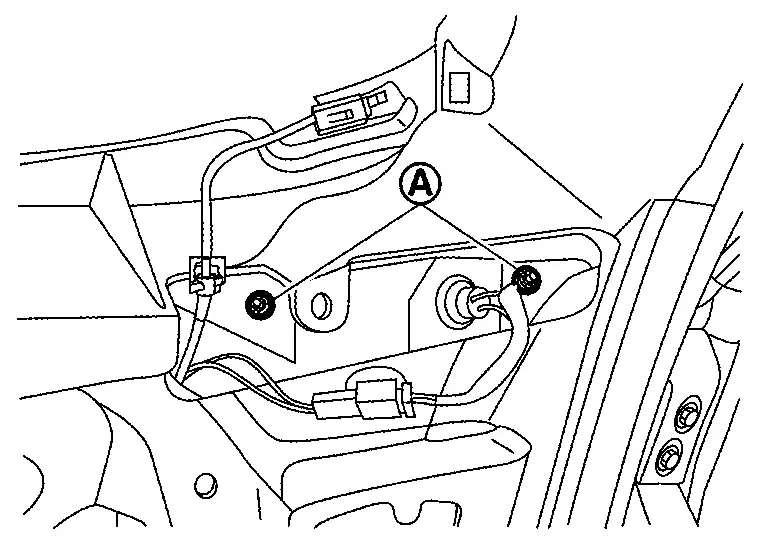
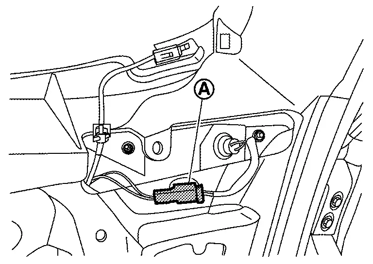
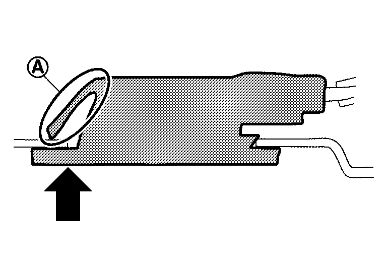
Apply protective tapes (A) on the part to protect it from damage.
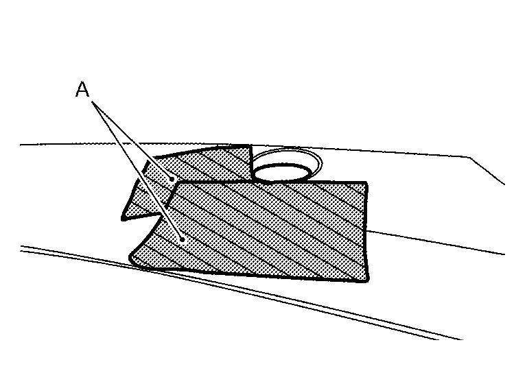
Disengage optical sensor fixing pawls using a remover tool (A).
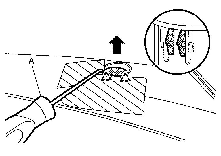
|
: Pawl |
Disconnect optical sensor harness connector, and then remove optical sensor.
INSTALLATION
Install in the reverse order of removal.
Lighting Turn Signal Switch
Removal and Installation
CAUTION:
Disconnect the battery negative terminal or remove power circuit fuse when performing the operation for preventing electric leakage. Refer to Precautions for Removing Battery Terminal.
REMOVAL
Remove lighting & turn signal switch (combination switch). Refer to Removal and Installation.
INSTALLATION
Install in the reverse order of removal.
Hazard Switch
Exploded View
|
Center ventilator finisher | |
Hazard switch | ||
|
: Pawl | ||||
Removal and Installation
CAUTION:
Disconnect the battery negative terminal or remove power circuit fuse when performing the operation for preventing electric leakage. Refer to Precautions for Removing Battery Terminal.
REMOVAL
Remove center ventilator finisher. Refer to Removal and Installation.
Disengage hazard switch fixing pawls, and then remove hazard switch.
INSTALLATION
Install in the reverse order of removal.
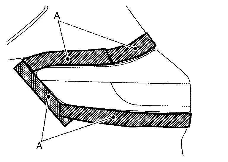
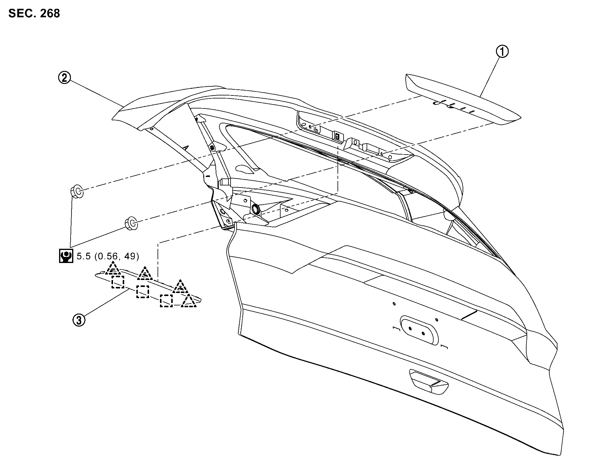
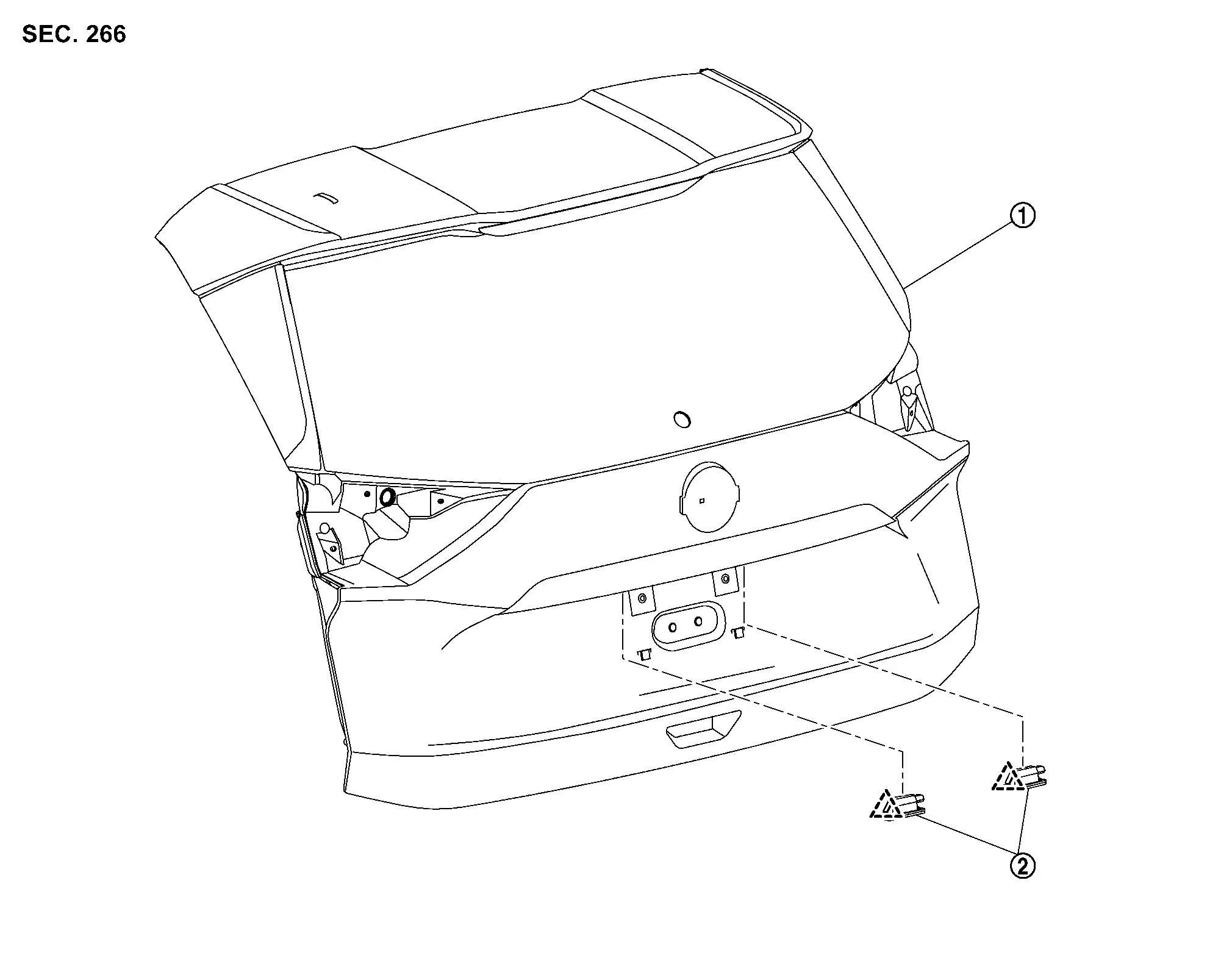
Rear Combination Lamp (body Side)
Exploded View
REMOVAL
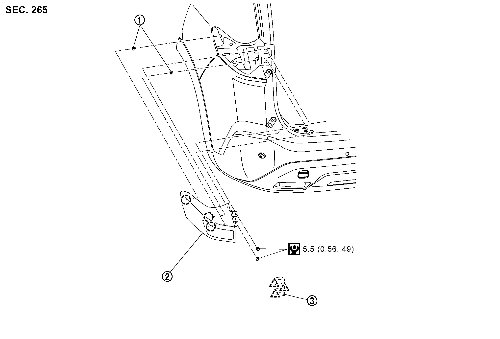
|
Grommet | |
Rear combination lamp (body side) |
|
Rear combination lamp cover |
 |
: Clip | ||||
|
: Pawl | ||||
|
: Nôñm (kg-m, in-lb) | ||||
DISASSEMBLY
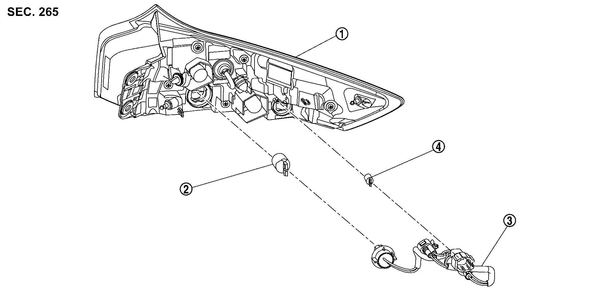
|
Rear combination lamp (body side) |
|
Rear turn signal lamp bulb | |
Lamp harness |
|
Rear side marker lamp bulb |
Removal and Installation
CAUTION:
Disconnect the battery negative terminal or remove power circuit fuse when performing the operation for preventing electric leakage. Refer to Precautions for Removing Battery Terminal.
REMOVAL
Fully open back door.
Disengage rear combination lamp cover fixing pawls, and then remove rear combination lamp cover.
|
: Pawl |
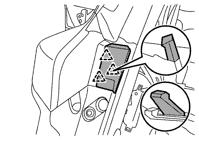
Remove rear combination lamp (body side) mounting bolts .
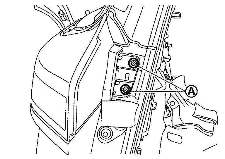
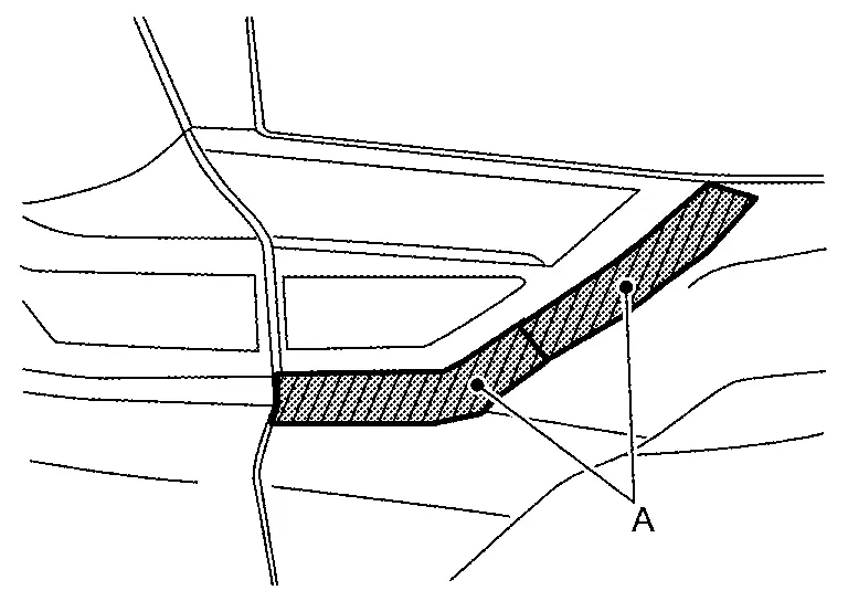
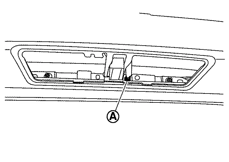
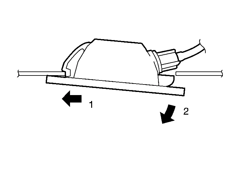
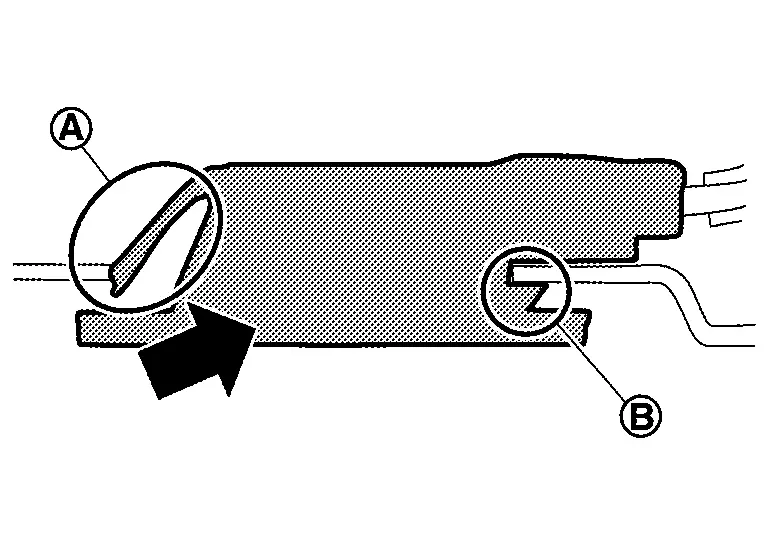
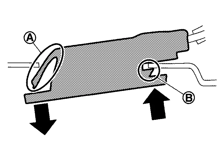
Apply protective tapes (A) on the part to protect it from damage.
Disengage rear combination lamp (body side) fixing clips using a remover tool (A) according to numerical order 1ã2 indicated by arrows as shown in the figure, and then pull out rear combination lamp (body side).
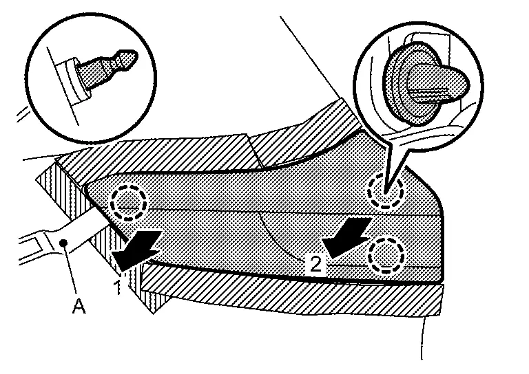
|
: Clip |
Disconnect rear combination lamp (body side) harness connector, and then remove rear combination lamp (body side).
INSTALLATION
Note the following item, and then install in the reverse order of removal.
CAUTION:
Visually check clips for deformation and damage during installation. Replace with new ones if necessary.
Replacement
CAUTION:
-
Disconnect the battery negative terminal or remove power circuit fuse when performing the operation for preventing electric leakage. Refer to Precautions for Removing Battery Terminal.
-
Never touch the glass of bulb directly by hand. Keep grease and other oily matters away from it.
-
Never touch bulb by hand while it is lit or right after being turned OFF.
-
Never leave bulb out of lamp reflector for a long time because dust, moisture smoke, etc. may affect the performance of lamp. When replacing bulb, be sure to replace it with new one.
TAIL LAMP
CAUTION:
Replacement of a single part is not possible due to the adoption of LED. For replacement, replace rear combination lamp (body side) as a set. Refer to Removal and Installation.
STOP LAMP
CAUTION:
Replacement of a single part is not possible due to the adoption of LED. For replacement, replace rear combination lamp (body side) as a set. Refer to Removal and Installation.
REAR TURN SIGNAL LAMP
-
Remove rear combination lamp (body side). Refer to Removal and Installation.
-
Rotate rear turn signal lamp bulb socket counterclockwise, and then remove rear turn signal lamp bulb socket.
-
Remove rear turn signal lamp bulb from rear turn signal lamp bulb socket.
REAR SIDE MARKER LAMP
-
Remove rear combination lamp (body side). Refer to Removal and Installation.
-
Rotate rear side marker lamp bulb socket counterclockwise, and then remove rear side marker lamp bulb socket.
-
Remove rear side marker lamp bulb from rear side marker lamp bulb socket.
Rear Combination Lamp (back Door Side)
Exploded View
REMOVAL
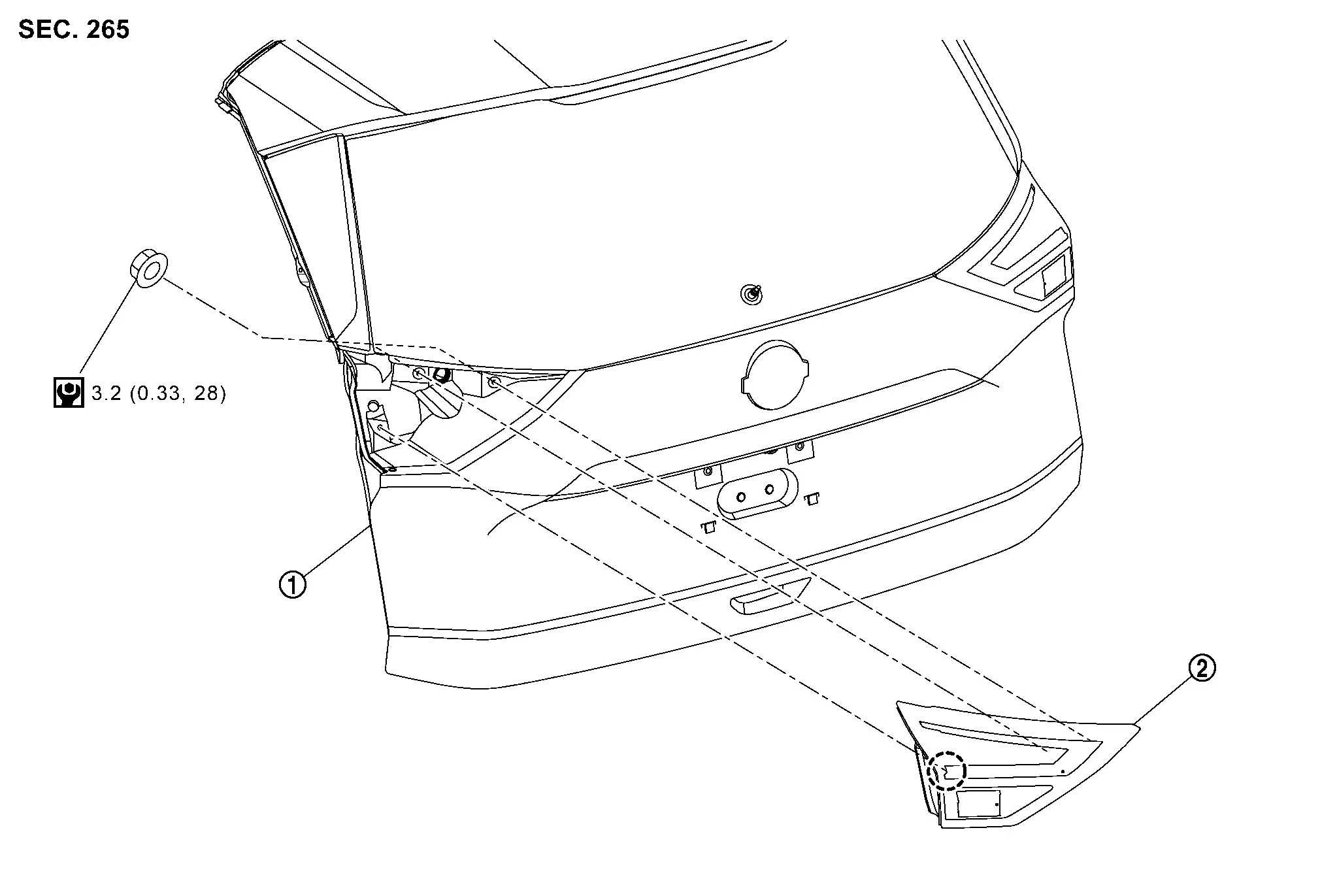
|
Back door panel | |
Rear combination lamp (back door side) |
||
|
: Clip | ||||
|
: Nôñm (kg-m, in-lb) | ||||
DISASSEMBLY
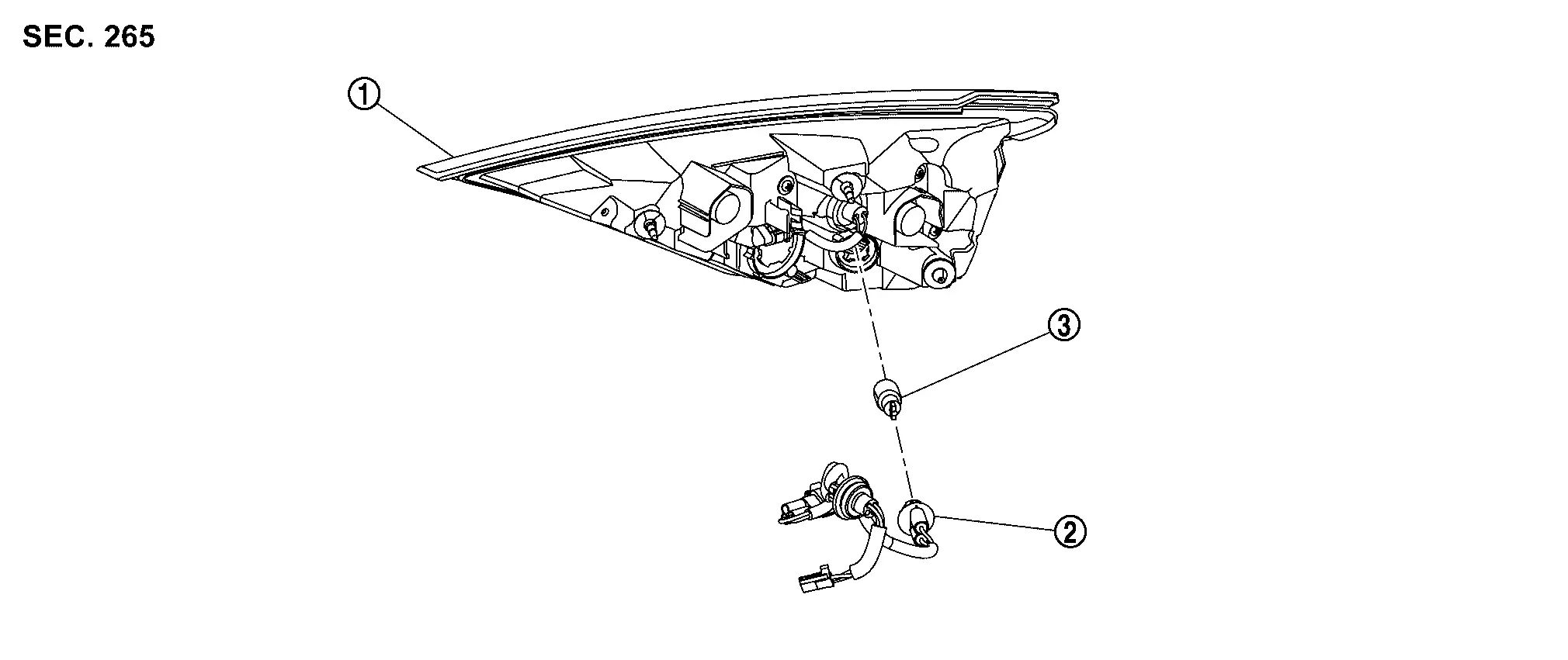
|
Rear combination lamp (back door side) |
|
Lamp harness | |
Back-up lamp bulb |
Removal and Installation
CAUTION:
Disconnect the battery negative terminal or remove power circuit fuse when performing the operation for preventing electric leakage. Refer to Precautions for Removing Battery Terminal.
REMOVAL
Remove back door inner finisher. Refer to Removal and Installation.
Remove rear combination lamp (back door side) mounting nuts .
Disconnect rear combination lamp (back door side) harness connector .
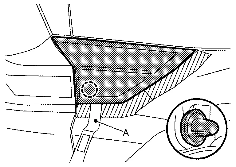
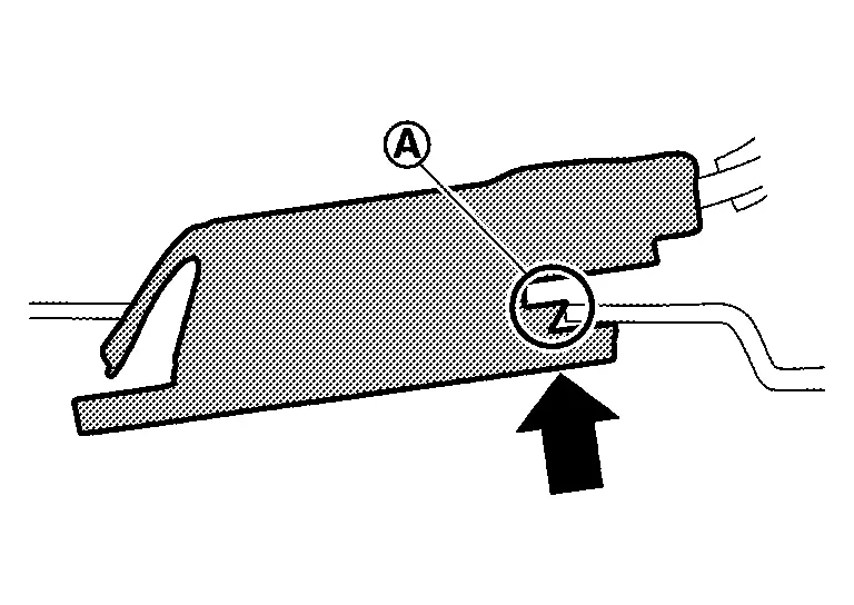
Apply protective tapes (A) on the part to protect it from damage.
Disengage rear combination lamp (back door side) fixing clip using a remover tool (A), and then remove rear combination lamp (back door side).
|
: Clip |
INSTALLATION
Note the following item, and then install in the reverse order of removal.
CAUTION:
Visually check clips for deformation and damage during installation. Replace with new ones if necessary.
Replacement
CAUTION:
-
Disconnect the battery negative terminal or remove power circuit fuse when performing the operation for preventing electric leakage. Refer to Precautions for Removing Battery Terminal.
-
Never touch the glass of bulb directly by hand. Keep grease and other oily matters away from it.
-
Never touch bulb by hand while it is lit or right after being turned OFF.
-
Never leave bulb out of lamp reflector for a long time because dust, moisture smoke, etc. may affect the performance of lamp. When replacing bulb, be sure to replace it with new one.
TAIL LAMP
CAUTION:
Replacement of a single part is not possible due to the adoption of LED. For replacement, replace rear combination lamp (back door side) as a set. Refer to Removal and Installation.
BACK-UP LAMP
-
Remove rear combination lamp (back door side). Refer to Removal and Installation.
-
Rotate back-up lamp bulb socket counterclockwise, and then remove back-up lamp bulb socket.
-
Remove back-up lamp bulb from back-up lamp bulb socket.
High-Mounted Stop Lamp
Exploded View
|
High-mounted stop lamp | |
Back door panel | |
Back door inner finisher cap |
|
: Nôñm (kg-m, in-lb) | ||||
|
: Pawl | ||||
 |
: Metal clip | ||||
Removal and Installation
CAUTION:
Disconnect battery negative terminal or remove power circuit fuse when performing the operation for preventing electric leakage. Refer to Precautions for Removing Battery Terminal.
REMOVAL
Fully open back door.
Apply protective tape (A) on the part to protect it from damage.
Disengage back door inner finisher cap fixing pawls and metal clips using a remover tool (A) according to numerical order 1ã3 indicated by arrows as shown in the figure, and then remove back door inner finisher cap.
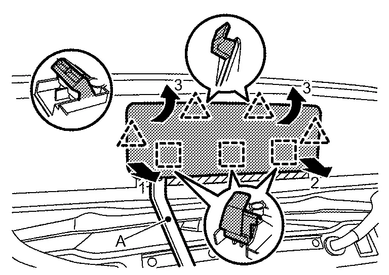
|
: Pawl |
|
: Metal clip |
Remove high-mounted stop lamp mounting nuts .
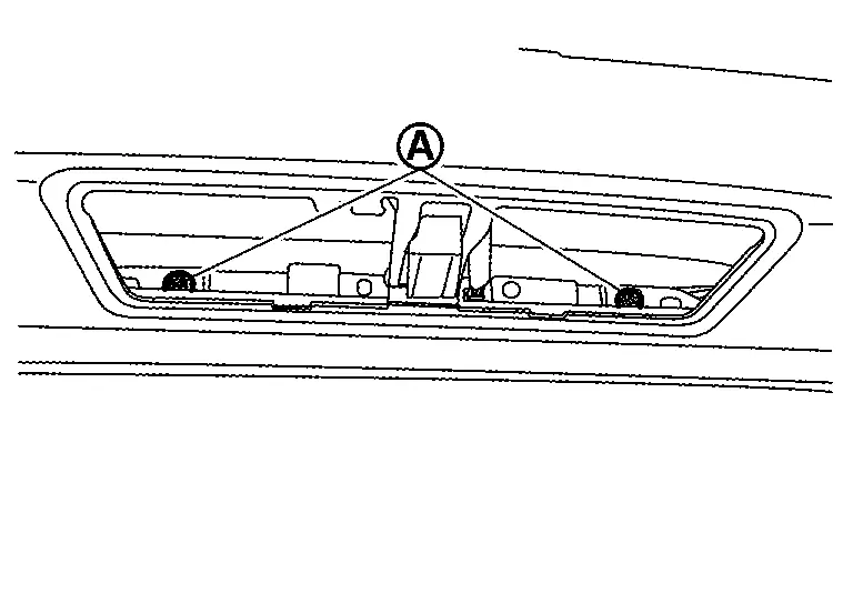
Disconnect high-mounted stop lamp harness connector , and then remove high-mounted stop lamp.
INSTALLATION
Install in the reverse order of removal.
Replacement
CAUTION:
Disconnect battery negative terminal or remove power circuit fuse when performing the operation for preventing electric leakage. Refer to Precautions for Removing Battery Terminal.
HIGH-MOUNTED STOP LAMP
CAUTION:
Replacement of a single part is not possible due to the adoption of LED. For replacement, replace high-mounted stop lamp unit as a set. Refer to Removal and Installation.
License Plate Lamp
Exploded View
|
Back door panel | |
License plate lamp | ||
|
: Pawl | ||||
Removal and Installation
CAUTION:
Disconnect the battery negative terminal or remove power circuit fuse when performing the operation for preventing electric leakage. Refer to Precautions for Removing Battery Terminal.
REMOVAL
Disengage license plate lamp fixing pawl according to numerical order 1ã2 indicated by arrows as shown in the figure.
Disconnect license plate lamp harness connector, and then remove license plate lamp.
INSTALLATION
Connect license plate lamp harness connector.
Put license plate lamp in the hole without fixing pawl and hook  by as shown in the figure.
Push the license plate lamp hook side and pull out the license plate lamp fixing pawl side by as shown in the figure.
Push license plate lamp to the position where hook falls.
Engage license plate lamp fixing pawl , and then install license plate lamp.
Replacement
CAUTION:
Disconnect battery negative terminal or remove power circuit fuse when performing the operation for preventing electric leakage. Refer to Precautions for Removing Battery Terminal.
LICENSE PLATE LAMP
Replacement of a single part is not possible because license plate lamp cannot disassemble. For replacement, replace license plate lamp as a set. Refer to Removal and Installation.
Rear Reflex Reflector
Exploded View
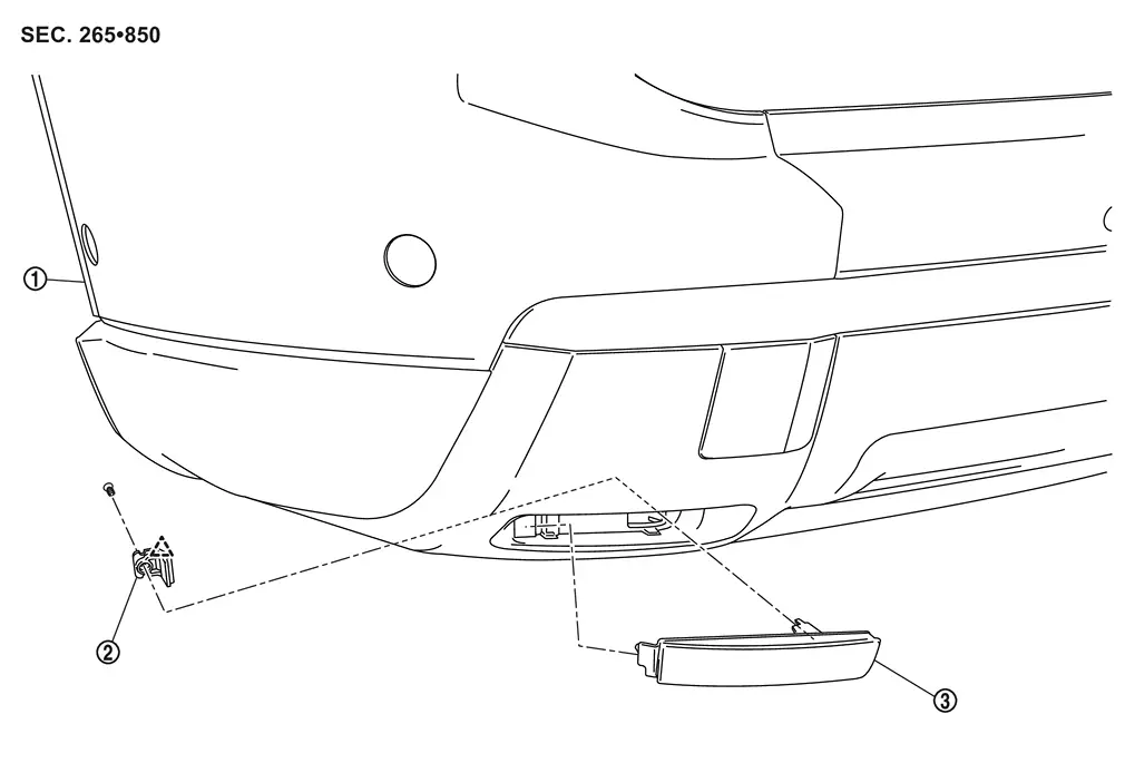
| 1. | Rear bumper fascia | 2. | Clamp | 3. | Rear reflex reflector |
|
: Pawl | ||||
Removal and Installation
REMOVAL
Remove clamp fixing screw, and then remove clamp.
Remove rear reflex reflector.
INSTALLATION
Install clamp on the rear reflex reflector, and then install clamp fixing screw.
Engage clamp fixing pawl, and then install rear reflex reflector.
Other materials:
It Can Communication 3 Circuit
Diagnosis Procedure
CHECK NETWORK DIAGNOSIS
Check the "Network diagnosis" results from CONSULT to see that the diagnostic CAN communication circuit have no malfunction.
Are the diagnostic CAN communication circuit normal?
YES>>
GO TO 2.
NO>>
Check and repair diagnostic CAN commu ...
Intelligent Lane Intervention (I-LI)
Basic information
WARNING
The Intelligent Lane Intervention system on the Nissan Rogue must be used with caution. Ignoring warnings or relying solely on the system may lead to loss of control, injury or death.
I-LI will not steer the Nissan Rogue for you or prevent skidding. The driver must alwa ...
Prûˋcautions pour ûˋviter tout risque de collision et de tonneau
AVERTISSEMENT
Une utilisation imprudente ou dangereuse de ce vûˋhicule peut entraûÛner une perte de contrûÇle, un accident grave ou un retournement.
Restez vigilant et adoptez une conduite prudente en toutes circonstances. Respectez scrupuleusement le code de la route et adaptez votre vitesse au ...