Nissan Rogue (T33) 2021-Present Service Manual: Removal and Installation :: Steering Wheel
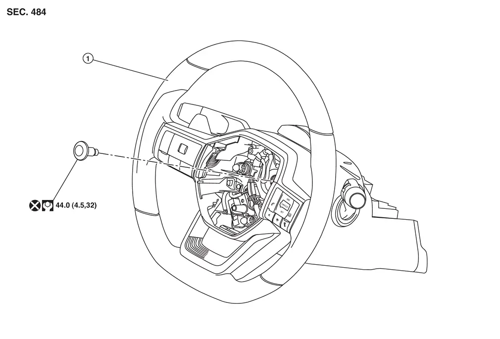
Exploded View
 |
Steering wheel | ||||
 |
: N·m (kg-m, ft-lb) | ||||
 |
: Always replace after every disassembly. | ||||
Removal and Installation
REMOVAL
Set vehicle to the straight-ahead position.
Remove driver air bag module. Refer to Removal and Installation.
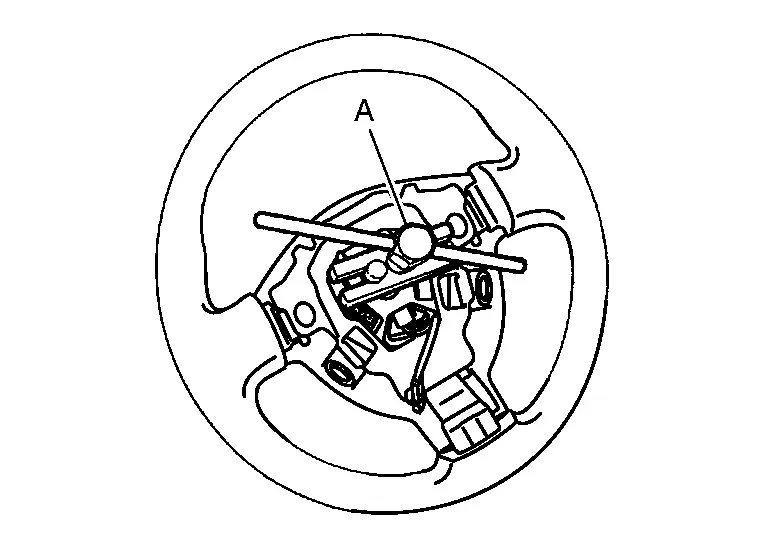
Remove steering wheel bolt after steering is locked.
Remove steering wheel with the steering wheel puller (commercial service tool) (A).
 NOTE:
NOTE:
-
Put paint marks on the steering wheel and the steering column shaft head for supporting accurate positioning during the installation procedure.
-
Secure the spiral cable with tape so that the spiral cable case and the spiral cable rotating part stay aligned. This will avoid the neutral position alignment procedure during steering wheel installation.
INSTALLATION
Installation is in the reverse order of removal.
CAUTION:
-
Never twist spiral cable excessively after it becomes tight. Twisting may cause the spiral cable to be torn off. If the spiral cable isn't in the neutral position, align the neutral position of the spiral cable. Refer to Removal and Installation.
-
Perform the "ADJUSTMENT OF STEERING ANGLE SENSOR NEUTRAL POSITION". Refer to Description.
-
Never reuse steering wheel mounting bolt.
-
Perform steering torque calibration after removal and installation or replacing the steering wheel. Refer to Work Procedure.
-
If a malfunction with ProPILOT Assist 1.1 was corrected, perform the "ACTION TEST". Refer to Work Procedure (ProPILOT Assist 1.1 and a 7 inch Information Display) or to Work Procedure (ProPILOT Assist 1.1 and a FULL TFT METER).
-
If a malfunction with ProPILOT Assist 2.1 was corrected, perform the "ACTION TEST". Refer to Work Procedure (ProPILOT Assist 2.1).
Other materials:
Dtc/circuit Diagnosis. C18d0-01 Brake Power Supply Back up Unit
DTC Description
DTC DETECTION LOGIC DTC No. CONSULT screen terms DTC detection condition
C18D0
01
Backup power supply unit
Diagnosis condition
When Ignition switch is ON.
Signal (terminal)
Brake power supply backup unit signal
Threshold
When a malfunction is detecte ...
Usb Charge Port. Removal and Installation. Usb Charge Port
Usb Charge Port
Rear Usb Charge Port
Removal and Installation
REMOVALRemove console rear finisher. Refer to Removal and Installation.
Press the USB charge port fixing pawl from the back of the console rear finisher to remove the USB charge port.
: Pawl
INSTALLATIONNote the followin ...
Ecu Diagnosis Information. Moonroof Motor Assembly
Reference Value
TERMINAL LAYOUTPHYSICAL VALUES
Terminal No.
(Wire color) Description Condition
Value
(Approx.)
+ – Signal name Input/Output
1
(B)
Ground
Ground
—
—
0 V
4
(W)
Ground
Moonroof Tilt UP signal
Input
Moonroof switch
Operate
( ...