Nissan Rogue (T33) 2021-Present Service Manual: Removal and Installation :: Steering Column
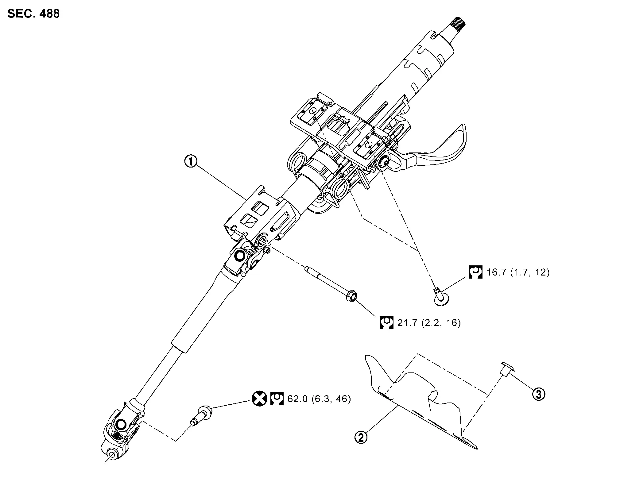
Exploded View
 |
Steering column assembly |  |
Steering shaft lower cover |  |
Clip |
 |
: N·m (kg-m, ft-lb) | ||||
 |
: Always replace after every disassembly. | ||||
Removal and Installation
REMOVAL
CAUTION:
-
Do not cause impact to steering column or shaft during removal or installation.
-
Be careful when removing steering column assembly from the Nissan Ariya vehicle because it is heavy.
-
Never unlock the tilt and telescope adjustment lever when the column is not securely mounted to the Nissan Ariya vehicle.
-
Place the steering column tilt and telescope lever in the locked position and zip tie the lever to the column assembly to avoid it being unlocked during removal and installation.
-
Never disassemble steering column components or lower shaft from upper steering column. They should not be separated.
-
Do not move the steering gear during removal or installation of steering column assembly.
Set vehicle to the straight ahead position.
Unlock the tilt/telescope adjustment lever then place the tilt to the highest level and telescope in to the shortest position. Then, lock the adjustment lever.
Remove the steering wheel. Refer to Removal and Installation.
Remove steering column covers. Refer to Removal and Installation.
Remove harness and set it aside.
Remove spiral cable. Refer to Removal and Installation.
Remove the combination switch. Refer to Removal and Installation.
Remove the instrument lower panel. Refer to Removal and Installation.
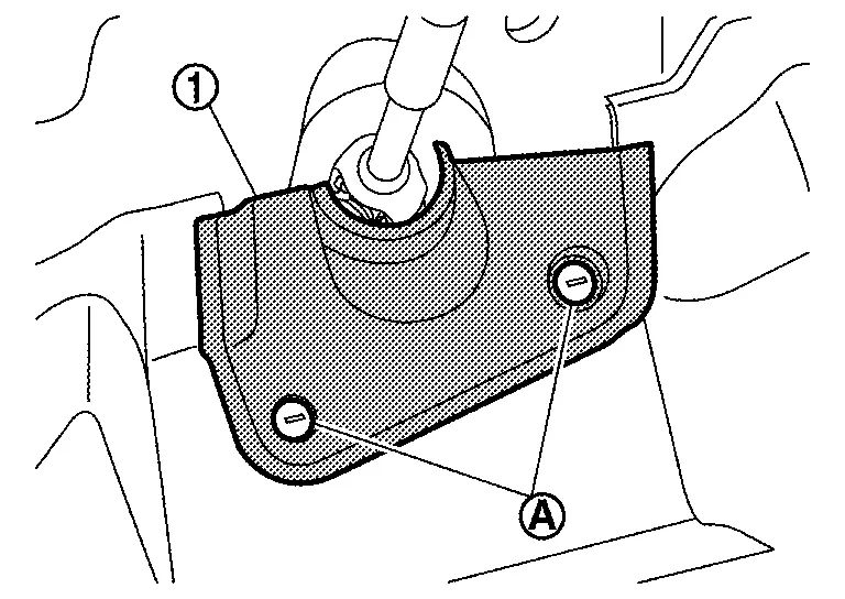
Remove clips (A) and then remove steering shaft lower cover (1).
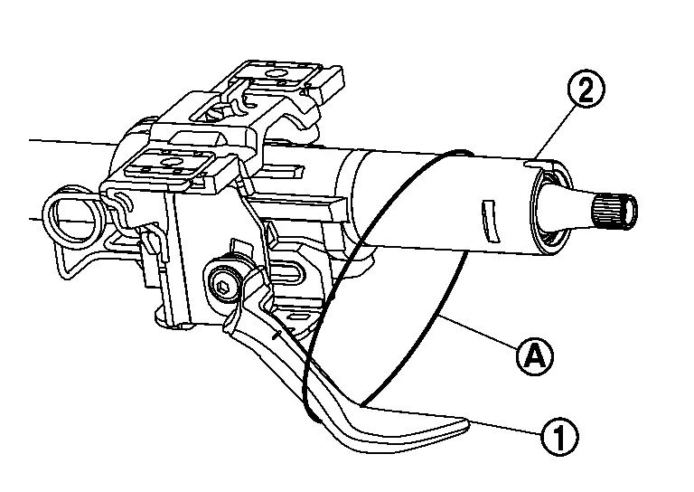
Add zip tie (A) around lever (1) and column (2) to prevent lever from being unlocked, tightened just enough to snug it. Don't overtighten or bend the lever.
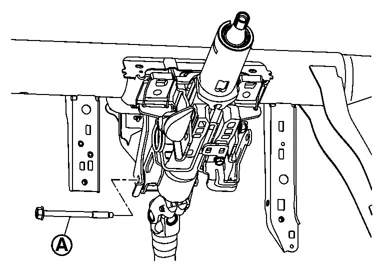
Remove lower shaft mounting bolt.
Remove the steering column assembly upper mounting bolts.
Remove the steering column assembly middle cross bolt.
CAUTION:
When removing the mounting bolts, be careful not to drop the steering column assembly.
Remove steering column assembly.
Perform inspection after removal. Refer to Inspection.
INSTALLATION
CAUTION:
-
Reject and replace steering column if tilt and telescope adjustment lever is unlocked prior to install and torque to steering cross member.
-
Do not unlock lever until mounting bolt and steering column assembly middle cross bolt are tightened to specified torque.
-
Fit bolts by hand to ensure bolts turn smoothly without catching before tightening to specified torque.
-
Must perform front wheel alignment resetting the steering wheel and toe.
-
Insert bolt (A) through the steering column hole.
-
Tentatively tighten bolt.
-
Insert bolt (A) through the steering column hole.
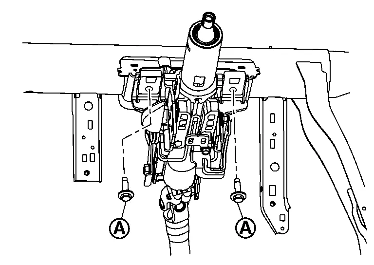
-
Tentatively tighten bolt.
-
Tighten bolt (A) to the specified torque.
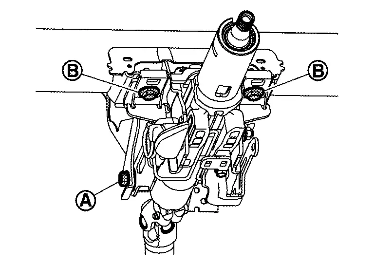
-
Tighten bolt (B) to the specified torque.
-
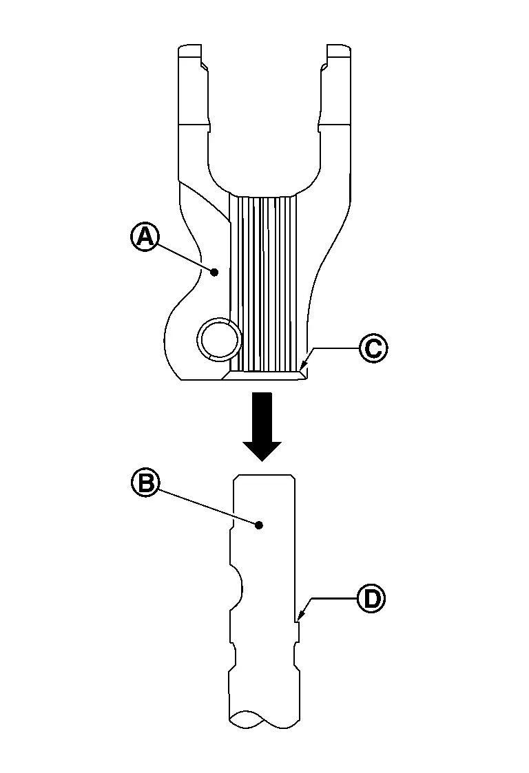
After aligning the blocking phase of pinion, the yoke (A) shall be inserted to the pinion shaft (B) until yoke lower surface (C) is in contact with pinion shaft surface (D).
-
Insert bolt (A).
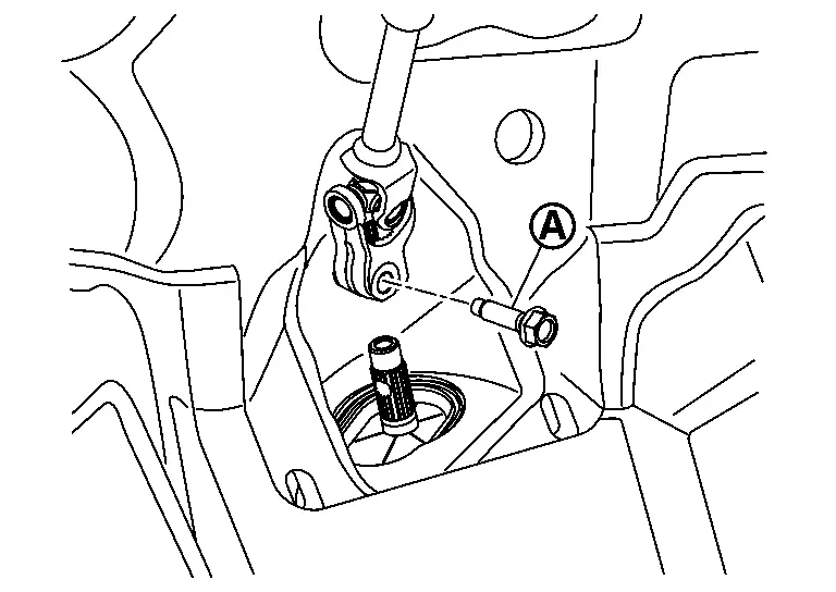
-
Tighten bolt to the specified torque.
CAUTION:
-
Do not insert the bolt (A) from the reverse direction.
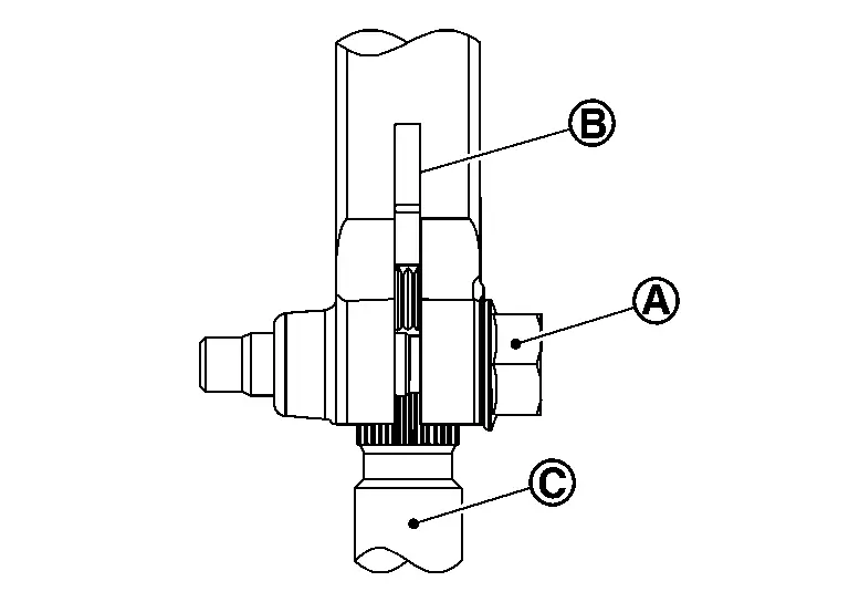
B : Yoke C : Pinion shaft -
Be sure to insert the bolt (A) in the correct position before fastening.
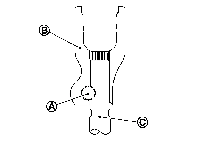
B : Yoke C : Pinion shaft
-
-
Unlock the tilt and telescope adjustment lever, move steering column up down smoothly without any catching or noise.
-
If equipped with ProPILOT Assist, perform steering torque calibration after replacing or removing and installing the steering column assembly. Refer to Work Procedure.
-
Perform alignment resetting the front wheel toe with steering wheel on center. Refer to Inspection.
-
Reset steering angle sensor. Refer to Description.
Inspection
INSPECTION AFTER REMOVAL
Check the following items and replace, if necessary.
-
Check each part of steering column assembly for damage or other malfunctions. Replace if there are any abnormal conditions.
-
Measure steering column rotating torque using a preload gauge (commercial service tool) (A). Replace steering column assembly if the rotating torque is outside the standard.
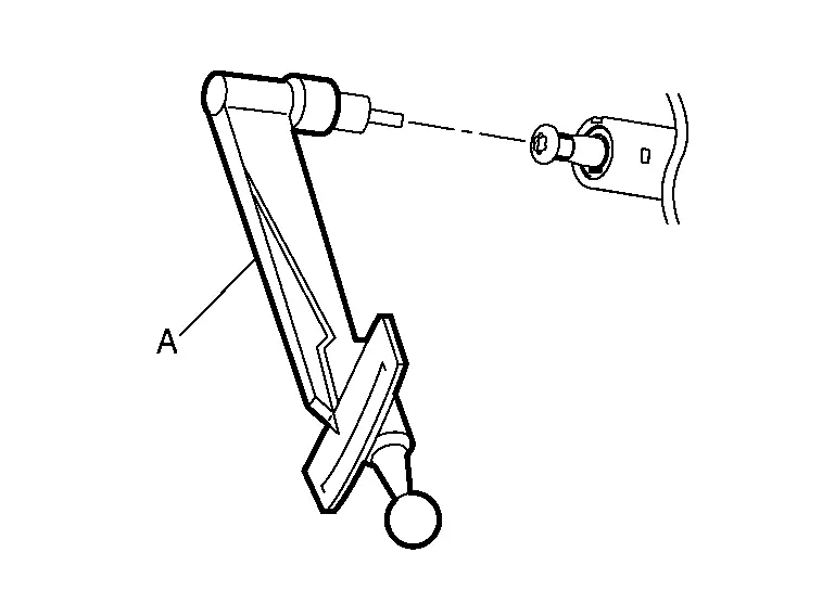
Rotating torque : Refer to Steering Column. -
With the column telescope set to the shortest position, measure the length “L” shown in the figure, if Nissan Ariya vehicle has been involved in a minor collision. Replace steering column assembly (with motor, reduction gear, sensor) if “L” is less than the minimum length.
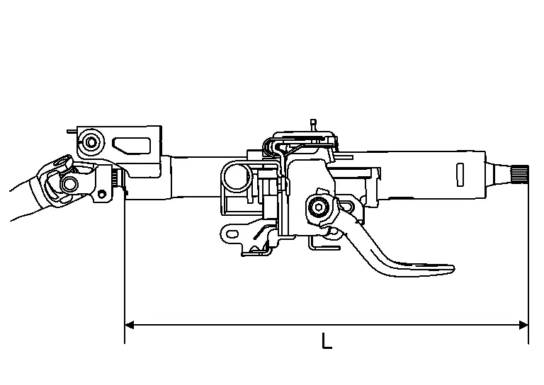
Steering column length minimum (telescope in) L : Refer to Steering Column. CAUTION:
-
Before completing this measurement, the steering column telescope must be set to the shortest position, the steering wheel will be farthest away from the driver.
-
Do not unlock the tilt and telescope adjustment lever if the steering column assembly is removed from the Nissan Ariya vehicle.
-
If the column telescope is not set to the shortest position, first reinstall the column, move the telescope to the shortest position, then complete the measurement.
-
INSPECTION AFTER INSTALLATION
Check the following items and replace, if necessary.
-
Check each part of steering column assembly for damage or other malfunctions. Replace if there are any abnormal conditions.
-
Check tilt and telescopic mechanism operating range “T”, “L” as shown in the figure.
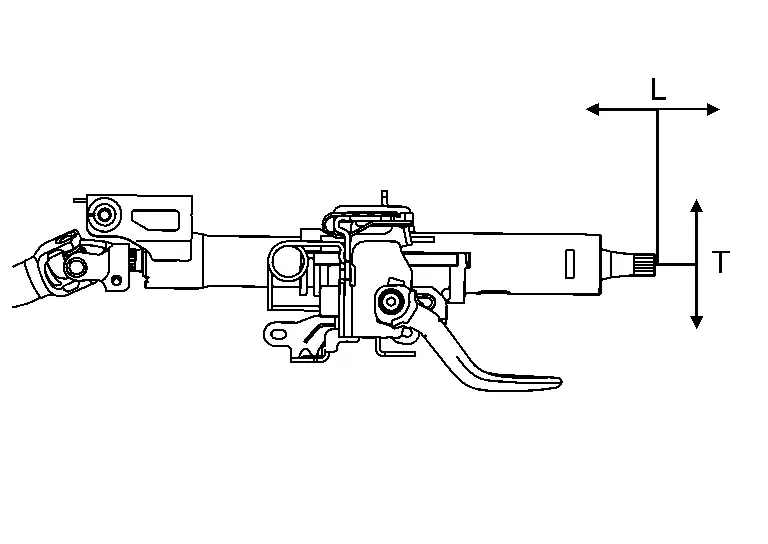
Tilt operating range (T) : Refer to Steering Column. Telescopic operating range (L) : Refer to Steering Column. -
Unlock the tilt and telescope adjustment lever, move steering column up and down smoothly without any catching or noise.
-
After installation, turn steering wheel to make sure it moves smoothly while turning to the left and right stops.
-
Make sure the number of turns is the same from the straight-forward position to left and right stops.
-
Make sure that the steering wheel is in a neutral position when driving straight ahead.
-
Rotate steering wheel to check for decentered condition, binding, noise, or excessive steering effort.
-
Check the steering wheel play, neutral position steering wheel, steering wheel turning torque, and front wheel turning angle.
-
Steering wheel play: Refer to Inspection.
-
Neutral position steering wheel, steering wheel turning torque, and front wheel turning angle: Refer to Inspection.
-
-
Adjust neutral position of steering angle sensor. Refer to Work Procedure.
Other materials:
Bouton d'appel d'urgence (SOS) du Nissan Rogue
Assistance et sécurité d'urgence
Informations essentielles sur le système
Les services technologiques NissanConnect équipant le Nissan Rogue offrent une suite complète de solutions de sécurité conçues pour protéger le conducteur et ses passagers en toutes circonstances.
En cas d'incide ...
B2720-16 Corner Sensor [rl]
DTC Description
DTC DETECTION LOGIC DTC CONSULT screen items (Trouble diagnosis content) DTC detection condition
B2720-16
CORNER SENSOR [RL]
(Corner sensor [rear left])
Diagnosis condition
When ignition switch is ON
Signal (terminal)
Rear sonar sensor LH outer power supply
...
C1b8b-82 Hardware Network Seperator System
DTC Description
DTC DETECTION LOGIC DTC No. CONSULT screen terms DTC detection condition
C1B8B
82
Power network separate relay
Diagnosis condition
When ignition switch is ON.
Signal (terminal)
CAN communication signal
Threshold
Power network separate relay is malfun ...