Nissan Rogue (T33) 2021-Present Service Manual: Removal and Installation :: Lower Joint
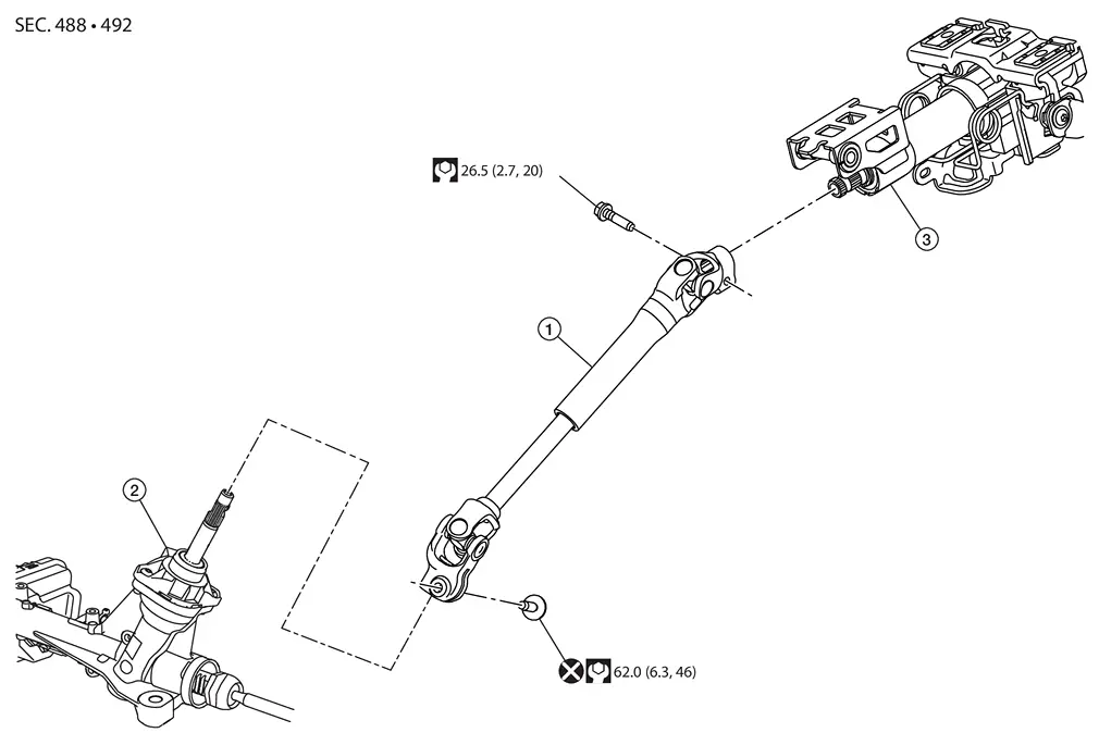
Exploded View
 |
Lower joint |  |
Steering gear |  |
Steering column assembly |
 |
: N·m (kg-m, ft-lb) | ||||
 |
: Always replace after every disassembly. | ||||
Removal and Installation
REMOVAL
CAUTION:
-
Do not cause impact to steering column or shaft during removal or installation.
-
Do not move the steering gear during removal or installation of lower joint assembly.
Set vehicle to the straight ahead position.
Remove the instrument lower panel. Refer to Removal and Installation.
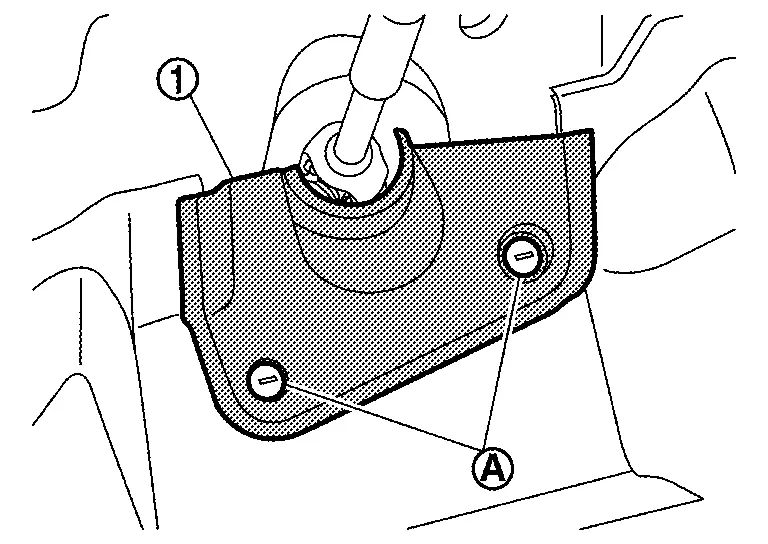
Remove clips (A) and then remove steering shaft lower cover (1).
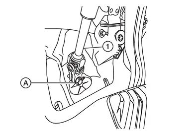
Remove lower shaft (1) mounting bolt (A).
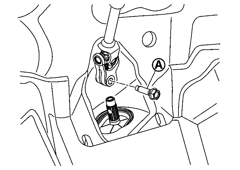
Remove bolt (A). Separate lower joint (1) from steering column.
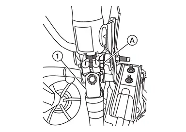
Remove lower joint.
INSTALLATION
CAUTION:
-
Fit bolts by hand to ensure bolts turn smoothly without catching before tightening to specified torque.
-
Must perform front wheel alignment resetting the steering wheel and toe.
-
After aligning the blocking phase of pinion, the yoke (A) shall be inserted to the pinion shaft (B) until yoke lower surface (C) is in contact with pinion shaft surface (D).
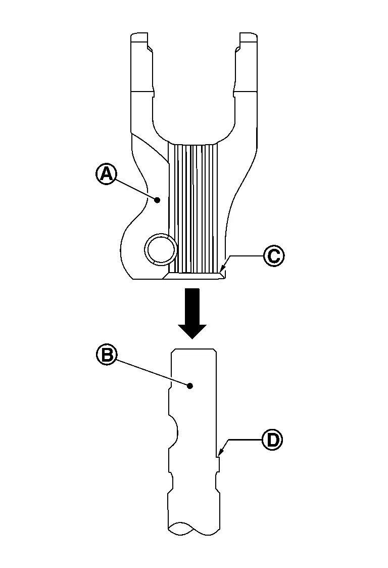
-
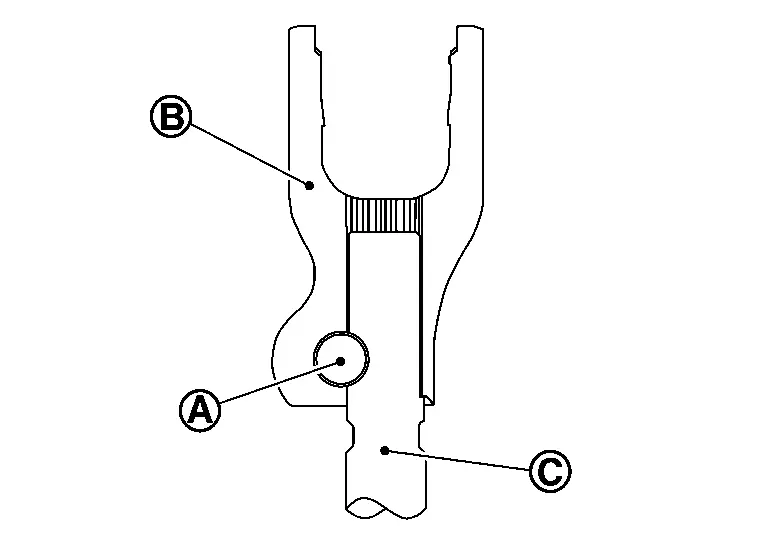
Insert bolt (A).
-
Tighten bolt to the specified torque.
CAUTION:
-
Do not insert the bolt (A) from the reverse direction.
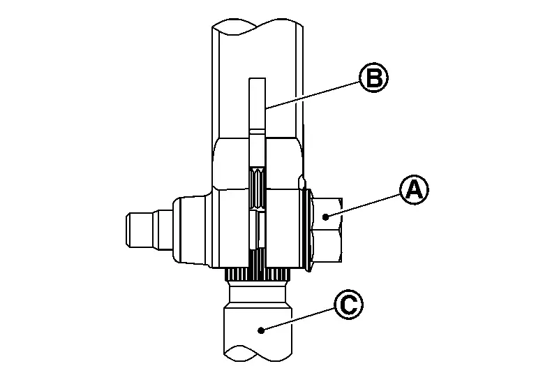
B : Yoke C : Pinion shaft -
Be sure to insert the bolt (A) in the correct position before fastening.
B : Yoke C : Pinion shaft
-
-
If equipped with ProPILOT Assist, perform steering torque calibration after replacing or removing and installing the steering column assembly. Refer to Work Procedure.
-
Perform alignment resetting the front wheel toe with steering wheel on center. Refer to Inspection.
-
Reset steering angle sensor. Refer to Description.
Other materials:
Removal and Installation. Driver Seat Control Unit
Removal and Installation
REMOVALRemove driver seat. Refer to Removal and Installation.
Disconnect driver seat control unit connector.
Remove fixing screws , and then remove driver seat control unit .
INSTALLATIONInstall in the reverse order of removal.CAUTION:
Be sure to perform ADDITIONAL SE ...
P0443 Evap Canister Purge Volume Control Solenoid Valve
DTC Description
DTC DETECTION LOGIC DTC
CONSULT screen terms
(Trouble diagnosis content)
DTC detection condition
P0443
00
PURG VOLUME CONT/V
(EVAP system purge control valve "A" circuit)
A
Diagnosis condition
Engine cold start
Signal (terminal)
—
Thresho ...
Informations de base
AVERTISSEMENT
Le non-respect des instructions et avertissements relatifs à l'utilisation correcte du système de freinage d'urgence automatique avec détection des piétons du Nissan Rogue peut entraîner des blessures graves, voire mortelles.
Le système de freinage d'urgence automatique avec ...