Nissan Rogue (T33) 2021-Present Service Manual: Removal and Installation :: Steering Gear and Linkage
Exploded View
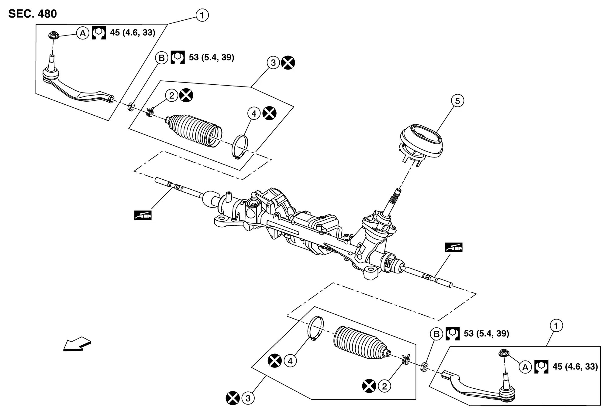
| 1. | Outer socket | 2. | Boot clamp (small diameter) | 3. | Boot |
| 4. | Boot clamp (large diameter) | 5. | Hole cover seal | A. | Outer socket lock nut. |
| B. | Inner socket lock nut. | тАФ | тАФ | тАФ | тАФ |
CAUTION:
Never apply the grease to the surface between steering rack and inner socket screw part.
Disassembly and Assembly
DISASSEMBLY (JAPAN PRODUCTION MODELS)
CAUTION:
Disassemble and assemble steering gear assembly by fixing the mounting area with a vise using copper plates.
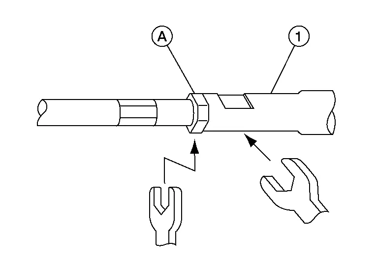
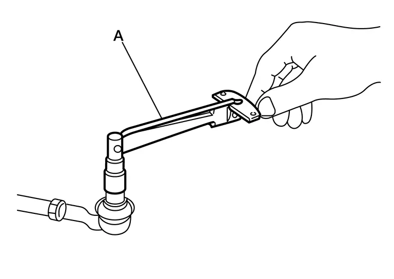
Loosen inner socket lock nut (A).
CAUTION:
To prevent damage, hold outer socket (1) across flats using suitable tool while loosening inner socket lock nut (A).
Remove boot clamps, and then remove boot from inner socket and housing.
CAUTION:
Never damage inner socket part of gear housing assembly when removing boot. Steering gear assembly must be replaced if gear housing assembly are damaged because it may cause foreign material interfusion.
Remove hole cover seal.
Perform inspection after disassembly. Refer to Inspection.
DISASSEMBLY (NORTH AMERICA PRODUCTION MODELS)
CAUTION:
Disassemble and assemble steering gear assembly by fixing the mounting area with a vise using copper plates.
Loosen inner socket lock nut (A).
CAUTION:
To prevent damage, hold outer socket (1) across flats using suitable tool while loosening inner socket lock nut (A).
Remove boot clamps, and then remove boot from inner socket and housing.
CAUTION:
Never damage inner socket part of gear housing assembly when removing boot. Steering gear assembly must be replaced if gear housing assembly are damaged because it may cause foreign material interfusion.
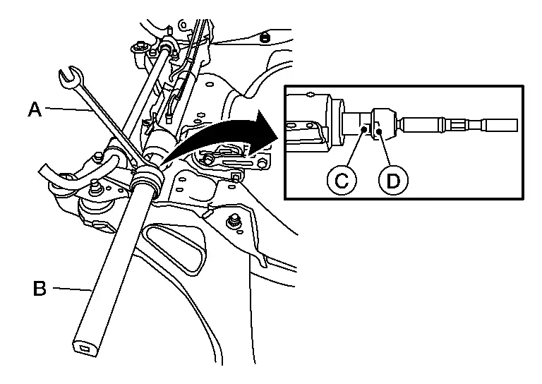
Remove the inner socket.
CAUTION:
To prevent damage to the steering gear when installing the inner socket, hold suitable tool (A) across steering gear flats (C) while turning suitable tool (B) across inner socket flats (D).
Remove hole cover seal.
Perform inspection after disassembly. Refer to Inspection.
ASSEMBLY (JAPAN PRODUCTION MODELS)
Install hole cover seal to gear housing assembly.
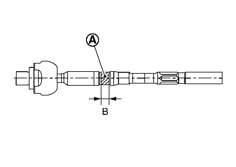
Apply recommended grease to part (A) of inner socket, and install boot to inner socket and gear housing.
Use Dow Corning 111 (manufactured by TOURE┬╖DAUKONINGU) or equivalent.
CAUTION:
Never reuse boot.
| Grease application position (Reference) | |
| B | : 10 mm (0.39 in) |
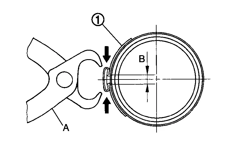
Install boot clamp (large diameter) (1) to boot using boot band crimping tool (SST: KV40107300) (A).
CAUTION:
-
Never reuse boot clamp (large diameter).
-
Install boot clamp (large diameter) securely to boot groove, and crimp it so as to have clearance (B) of 3 mm (0.12 in) or less as shown.
Install boot clamp (small diameter) to boot.
Adjust inner socket to standard length (L), and then tighten lock nut to the specified torque. Check length again after tightening lock nut.
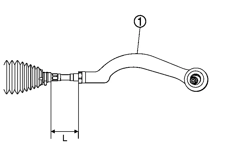
| 1. | : Outer socket |
| Inner socket length (L) | : Steering Gear and Linkage |
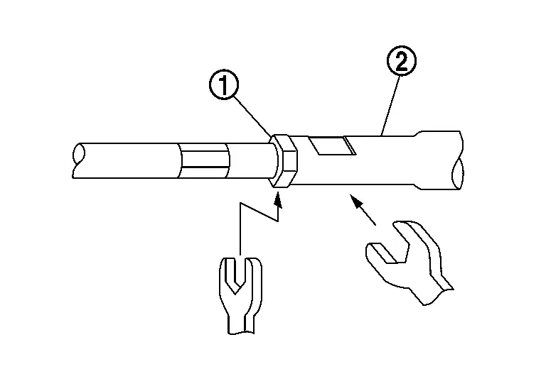
CAUTION:
-
When tightening the lock nut (1), be sure to fix outer socket (2) with a wrench or an equivalent to prevent the ball joint from getting contact with the knuckle.
-
Adjust toe-in after this procedure. The length achieved after toe-in adjustment is not necessarily the above value.
ASSEMBLY (NORTH AMERICA PRODUCTION MODELS)
Install hole cover seal to gear housing assembly.
Install inner socket. Tighten to specified torque. Refer to Exploded View.
CAUTION:
To prevent damage to the steering gear when installing the inner socket, hold suitable tool (A) across steering gear flats (C) while turning suitable tool (B) across inner socket flats (D).
Apply recommended grease to part (A) of inner socket, and install boot to inner socket and gear housing.
Use Dow Corning 111 (manufactured by TOURE┬╖DAUKONINGU) or equivalent.
CAUTION:
Never reuse boot.
| Grease application position (Reference) | |
| B | : 10 mm (0.39 in) |
Install boot clamp (large diameter) (1) to boot using boot band crimping tool (SST: KV40107300) (A).
CAUTION:
-
Never reuse boot clamp (large diameter).
-
Install boot clamp (large diameter) securely to boot groove, and crimp it so as to have clearance (B) of 3 mm (0.12 in) or less as shown.
Install boot clamp (small diameter) to boot.
Adjust inner socket to standard length (L), and then tighten lock nut to the specified torque. Check length again after tightening lock nut.
| 1. | : Outer socket |
| Inner socket length (L) | : Steering Gear and Linkage |
CAUTION:
-
When tightening the lock nut (1), be sure to fix outer socket (2) with a wrench or an equivalent to prevent the ball joint from getting contact with the knuckle.
-
To prevent damage, hold outer socket across flats using suitable tool while tightening inner socket lock nut.
-
Adjust toe-in after this procedure. The length achieved after toe-in adjustment is not necessarily the above value.
-
Inspect to make sure no boot deformation has occurred during toe-in adjustment. Adjust boot as necessary.
-
Adjust toe-in after this procedure. The length achieved after toe-in adjustment is not necessary the above value.
Inspection
INSPECTION AFTER DISASSEMBLY (JAPAN PRODUCTION MODELS)
Boot
-
Check boot for cracks, and replace it if a malfunction is detected.
Gear Housing Assembly
-
Check gear housing assembly for damage and scratches. Replace if there are any abnormal conditions.
Outer Socket and Inner Socket
-
Check the following items and replace the component if it does not meet the standard.
BALL JOINT SWINGING FORCE
-
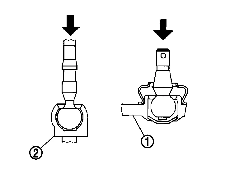
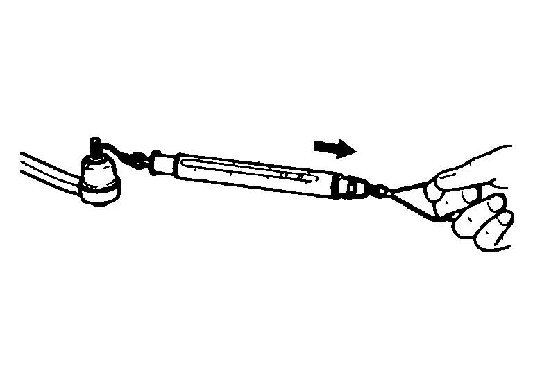
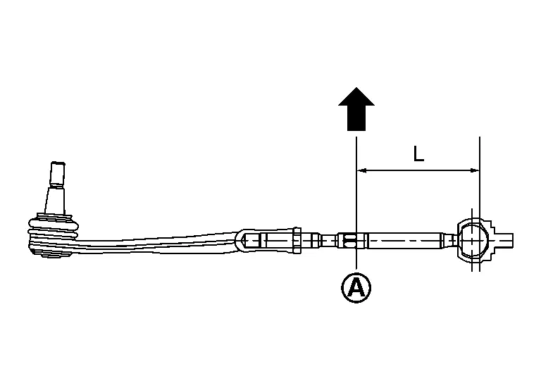
Hook a pull gauge [SST: тАФ (NI-44372)] at the point shown in the figure and pull the pull gauge. Make sure that the pull gauge reads the specified value when ball stud and inner socket start to move. Replace outer socket and inner socket if they are outside the standard.
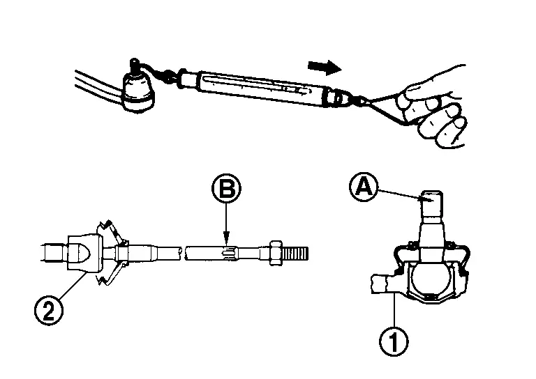
Measuring point of outer socket (1) Ball stud upper side (A) Measuring point of inner socket (2) Point (B) shown in the figure Swinging force : Refer to Steering Gear and Linkage.
BALL JOINT ROTATING TORQUE
-
Make sure that the reading is within the following specified range using suitable tool (A). Replace outer socket if the reading is outside the specification.
Rotating torque : Refer to Steering Gear and Linkage.
BALL JOINT AXIAL END PLAY
-
Apply an axial load of 490 N (50 kg, 110 lb) to ball stud. Using a dial gauge, measure amount of stud movement, and then make sure that the value is within the following specified range. Replace outer socket (1) and inner socket (2) if the measured value is outside the standard.
Axial end play : Refer to Steering Gear and Linkage
INSPECTION AFTER DISASSEMBLY (NORTH AMERICA PRODUCTION MODELS)
Boot
-
Check boot for cracks, and replace it if a malfunction is detected.
Gear Housing Assembly
-
Check gear housing assembly for damage and scratches. Replace if there are any abnormal conditions.
Outer Socket and Inner Socket
-
Check the following items and replace the component if it does not meet the standard.
BALL JOINT SWINGING FORCE
-
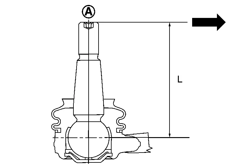
Hook a pull gauge [SST: тАФ (NI-44372)] at the point shown in the figure and pull the pull gauge. Make sure that the pull gauge reads the specified value when ball stud and inner socket start to move. Replace outer socket and inner socket if they are outside the standard.
Measuring point of outer socket -
Ball stud upper side (A)
-
Moment arm length (L): 71.5 mm (2.815 in)
Measuring point of inner socket -
Point shown in the figure (A)
-
Moment arm length (L): 105 mm (4.13 in)
Swinging force : Refer to Steering Gear and Linkage. -
BALL JOINT ROTATING TORQUE
-
Make sure that the reading is within the following specified range using suitable tool (A). Replace outer socket if the reading is outside the specification.
Rotating torque : Refer to Steering Gear and Linkage.
BALL JOINT AXIAL END PLAY
-
Apply an axial load of 490 N (50 kg, 110 lb) to ball stud. Using a dial gauge, measure amount of stud movement, and then make sure that the value is within the following specified range. Replace outer socket (1) and inner socket (2) if the measured value is outside the standard.
Axial end play : Refer to Steering Gear and Linkage.
INSPECTION AFTER INSTALLATION
-
Check if steering wheel turns smoothly when it is turned several times fully to the end of the left and right.
-
Check the steering wheel play, neutral position steering wheel, steering wheel turning force, and front wheel turning angle.
-
Steering wheel play: Refer to Steering Wheel.
-
Neutral position steering wheel, steering wheel turning force, and front wheel turning angle: Refer to Steering Wheel.
-
Other materials:
Nissanconnect Symptoms
Nissanconnect with 8" Color Display
Symptom Table
RELATED TO AUDIO Symptoms Check items Possible malfunction location/Action to take
No sound comes out or the level of the sound is low.
No sound from all speakers.
Malfunction in AV control unit.
Perform detected DTC self-diagnosis. ...
P00c0 Turbocharger Bypass Control Valve
DTC Description
DTC DETECTION LOGIC DTC
CONSULT screen terms
(Trouble diagnosis content)
DTC detection condition
P00C0
00
Turbocharger/Supercharger Bypass Valve B
(Turbocharger/Supercharger Bypass Valve B Control Circuit)
Diagnosis condition
тАФ
Signal (terminal)
...
Component Parts
Brake Control System
Component Parts Location
A.
Engine Room (LH Side)
No. Component Function
1.
Steering angle sensor
Refer to Steering Angle Sensor.
2.
Combination Meter
Refer to Component Parts Location (Type A Meter) or Component Parts Location (Type B Meter) f ...