Nissan Rogue (T33) 2021-Present Service Manual: Removal and Installation :: Steering Member Assembly
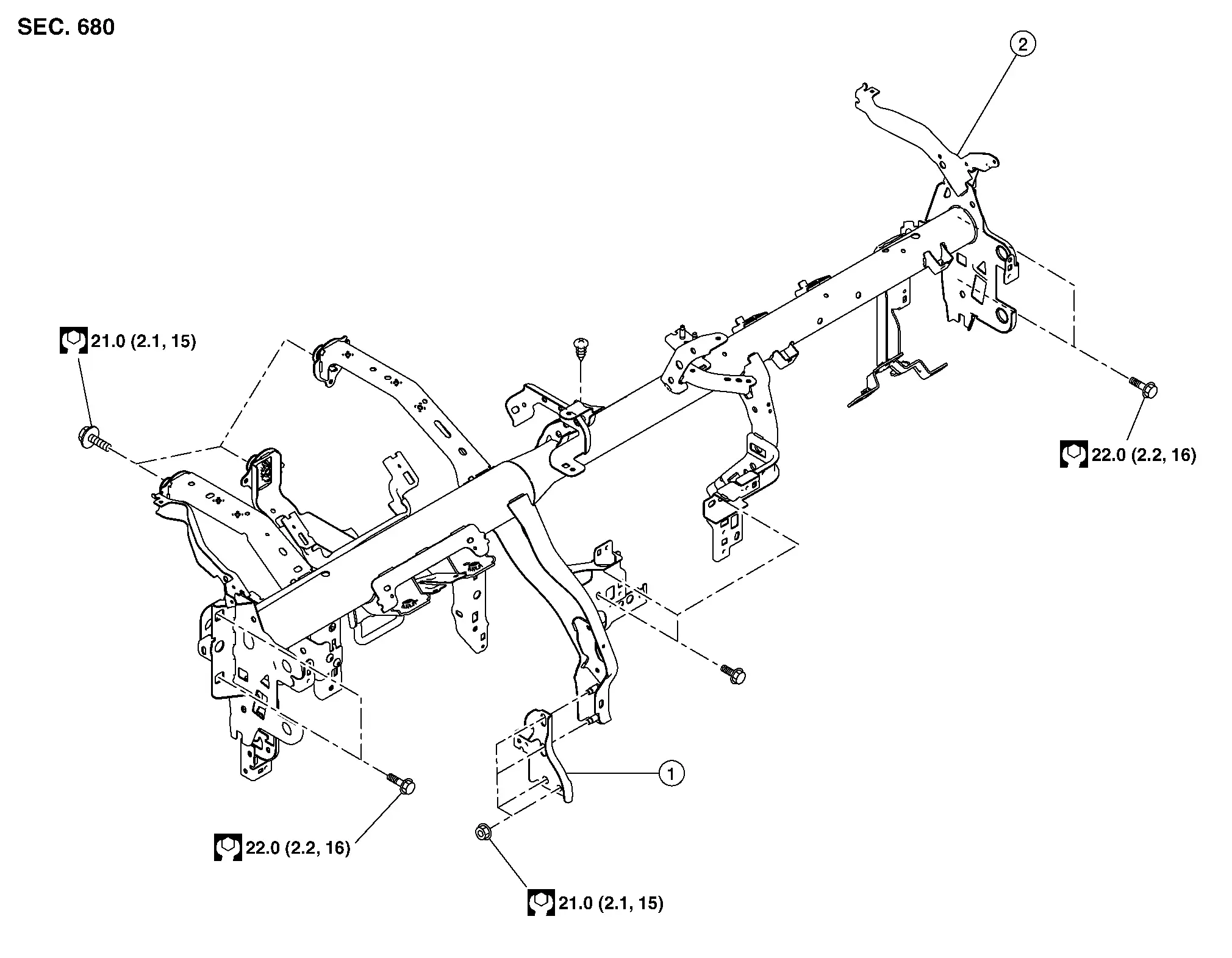
Exploded View
 |
Steering member brace |  |
Steering member assembly |
Removal and Installation
Remove instrument panel assembly. Refer to Removal and Installation.
Remove driver knee air bag. Refer to Removal and Installation.
Remove passenger knee air bag. Refer to Removal and Installation.
Remove dash side finishers. Refer to Removal and Installation.
Remove BCM. Refer to Removal and Installation.
Remove front defroster nozzle. Refer to Removal and Installation.
Remove center ventilator duct. Refer to Removal and Installation.
Remove side ventilator duct (LH/RH). Refer to Removal and Installation.
Remove upper steering column bolts and lower steering column. Refer to Exploded View.
Remove around view monitor control unit (if equipped). Refer to Removal and Installation.
Remove ADAS control unit 2. Refer to Removal and Installation.
Remove wiper drive assembly. Refer to Removal and Installation.
Remove steering member assembly bolts. Refer to Exploded View.
Using a suitable tool, release harness retainers and disconnect harness connectors.
Remove steering member assembly.
INSTALLATION
Installation is in the reverse order of removal.
Other materials:
Wireless Charger. System Description
Component Parts
Wireless Charger
Component Parts Location
A.
Console finisher assembly
No.Component
1.
Wireless charger unit
2.
Wireless charger indicator
Wireless charger unit
Wireless charger unit
The wireless unit is located at the front of the center console.
Wirel ...
B20c8-14 Ecv (electrical Control Valve)
DTC Description
DTC DETECTION LOGIC DTC No.
CONSULT screen terms
(Trouble diagnosis content) DTC detection condition
B20C8–14
Compressor (ECV)
[Compressor (electrical control valve)
[CIRC SHORT TO GRND OR OPEN]
Diagnosis condition
When A/C switch is ON
Signal (Terminal) ...
P3194 Icc System
DTC Description
DTC DETECTION LOGIC DTC
CONSULT screen terms
(Trouble diagnosis content)
DTC detection condition
P3194
00
Cruise control communication
(Adaptive Cruise Control CAN wheel speed information unavailable or absent)
Diagnosis condition
Ignition switch ON
S ...