Nissan Rogue (T33) 2021-Present Service Manual: Removal and Installation :: Center Console Assembly
Exploded View
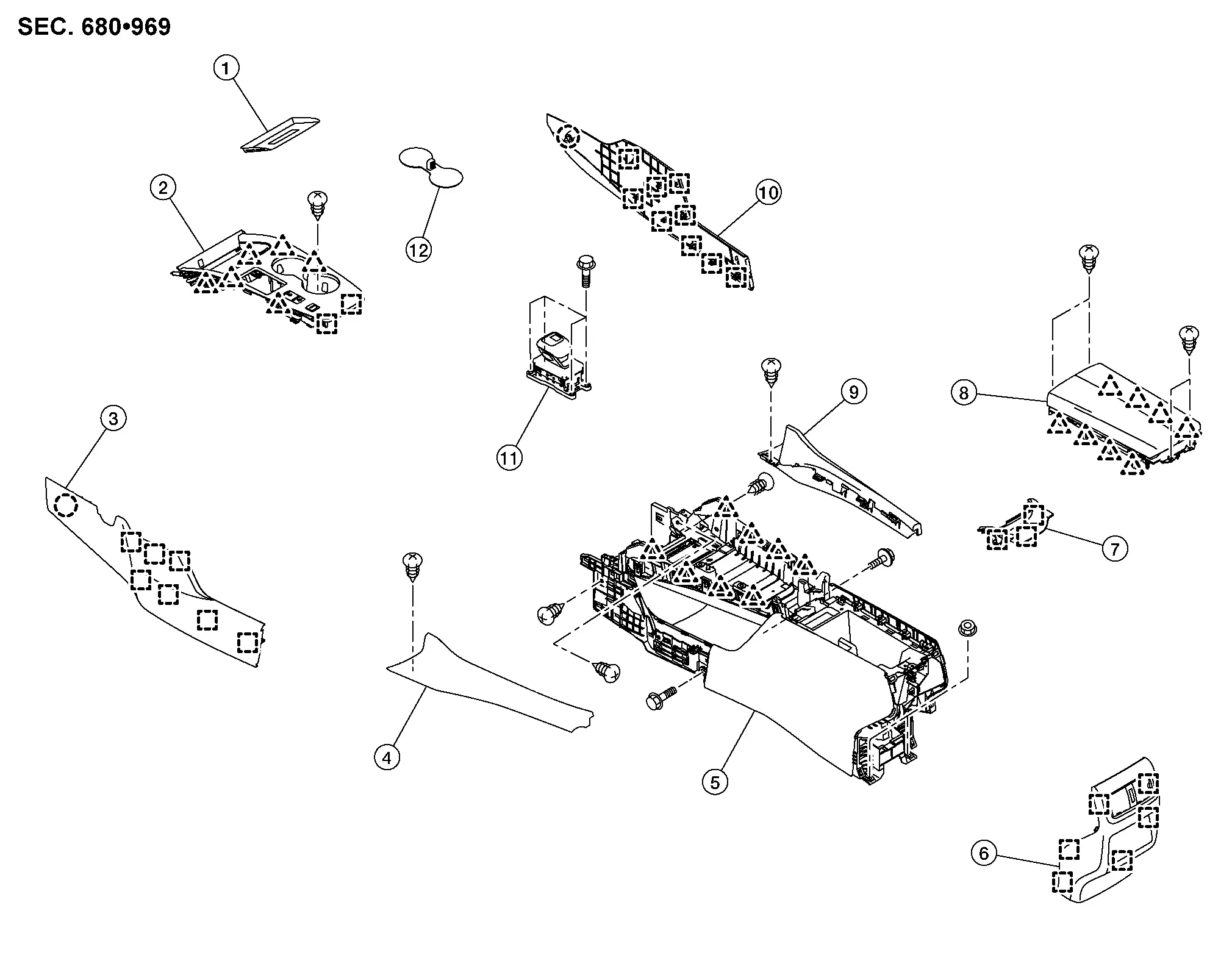
| 1. | Console finisher tray mat (if equipped) | 2. | Console finisher assembly | 3. | Instrument side panel LH |
| 4. | Panel console LH | 5. | Center console assembly | 6. | Console rear finisher |
| 7. | Console upper finisher | 8. | Console lid assembly | 9. | Panel console RH |
| 10. | Instrument side panel RH | 11. | Electric shift selector | 12. | Cup holder mat |
 |
: Clip | ||||
 |
: Pawl | ||||
 |
: Metal clip | ||||
Removal and Installation
WARNING:
Before servicing, place ignition switch OFF, disconnect battery negative terminal and wait for 3 minutes or more.
REMOVAL
CAUTION:
-
When removing, always use a remover tool that is made of plastic.
-
Always apply the parking brake before performing removal and installation.
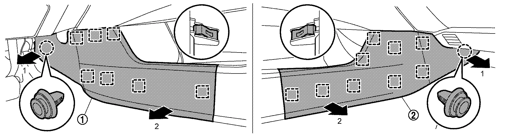
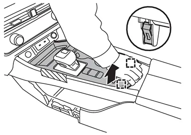
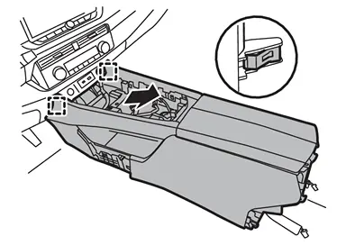
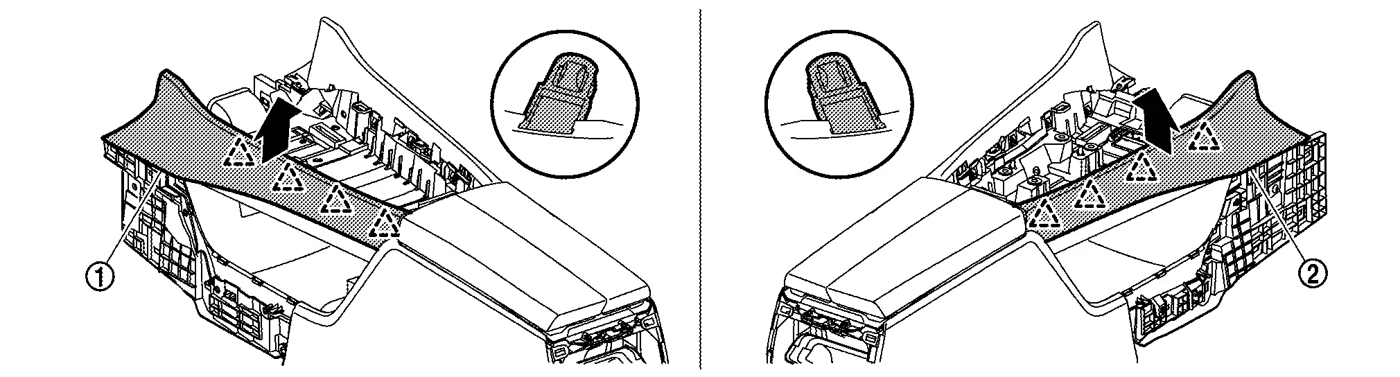
Disengage fixing clip and metal clips, and then remove instrument side panel (LH (1) and RH (2)) according to numerical order 1→2 indicated by arrows as shown in the figure.
|
: Clip |
|
: Metal clip |
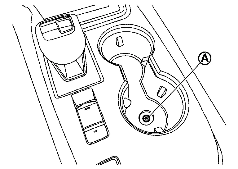
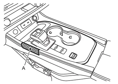
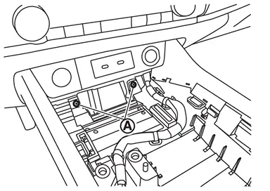
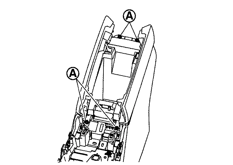
Remove console finisher assembly.Remove cup holder mat, and then remove fixing screw (A) .
|
: Metal clip |
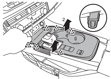
|
: Pawl |
Remove electric shift selector. Refer to Removal and Installation.
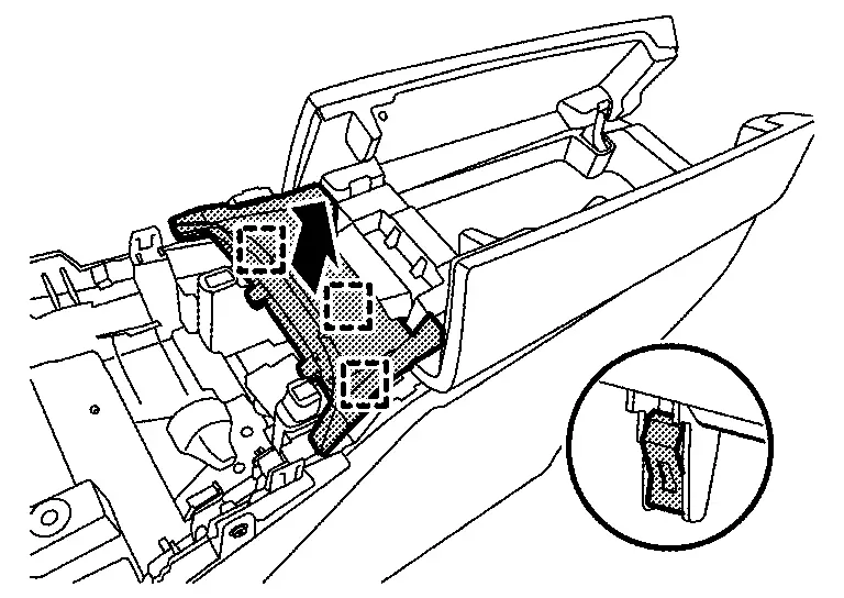
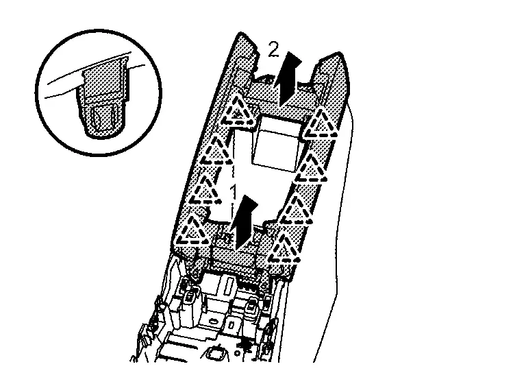
Remove console rear finisher.Open the console lid. Disengage fixing metal clips according to numerical order 1→2 indicated by arrows as shown in the figure, and then pull out console rear finisher.
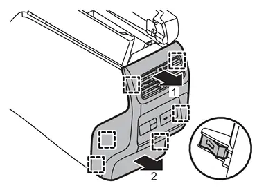
|
: Metal clip |
Remove center console assembly fixing screws  , mounting bolts (B) and nuts (C).
-
Front side
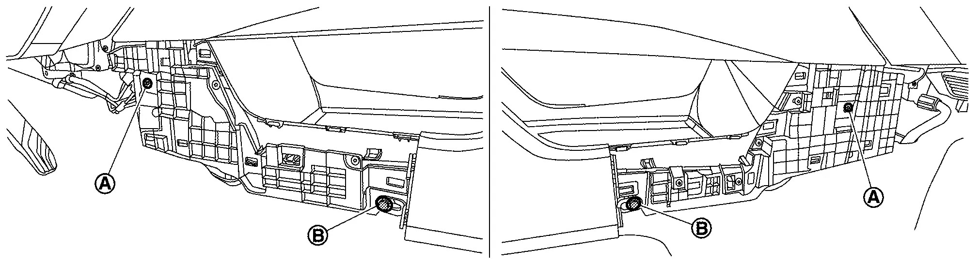
-
Rear side
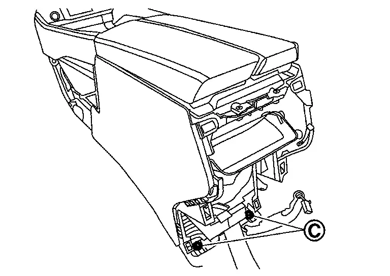
-
Upper side
Remove center console assembly.Disconnect harness connector and harness clips. Disengage fixing metal clips, and then remove center console assembly.
|
: Metal clip |
Remove the following parts after removing center console assembly.
-
Rear ventilator duct 1: Refer to Removal and Installation.
-
Rear ventilator duct 2: Refer to Removal and Installation.
-
Mood lamp (center console): Refer to Removal & Installation.
INSTALLATION
Installation is in the reverse order of removal.
Disassembly and Assembly
DISASSEMBLY
Remove panel console.Remove fixing screws .
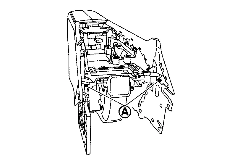
 and RH
  ).
).
|
: Pawl |
Remove console upper finisher.Open the console lid. Disengage fixing metal clips, and then remove console upper finisher.
|
: Metal clip |
Remove console lid assembly.Remove fixing screws .
|
: Pawl |
ASSEMBLY
Assemble in the reverse order of disassembly.
Other materials:
Symptom Diagnosis. Rear Heated Seat System
Symptom Table
Symptom Inspection item
Rear seat heater LH is inoperative.
Rear seat heater LH circuit
Seat cushion heater LH
Rear seat back heater LH
A/C amp.
Refer to Component Function Check.
Rear seat heater RH is inoperative.
Rear seat heater RH cir ...
2wd. Preparation. Preparation
Preparation
Special Service Tool
Tool number
(TechMate No.)
Tool name Description
KV40104000
( – )
Hub lock nut wrench
a: 85 mm (3.35 in)
b: 65 mm (2.56 in)
Removing and Installing wheel hub lock nut.
KV40107300
( – )
Boot band crimping tool
Installing bo ...
Type a. Preparation. Preparation
Preparation
Commercial Service Tools
Tool name Description
Variable resistor
Check fuel gauge indication position
Power tool
Loosening screws
...