Nissan Rogue (T33) 2021-Present Service Manual: Removal and Installation :: Instrument Panel Assembly
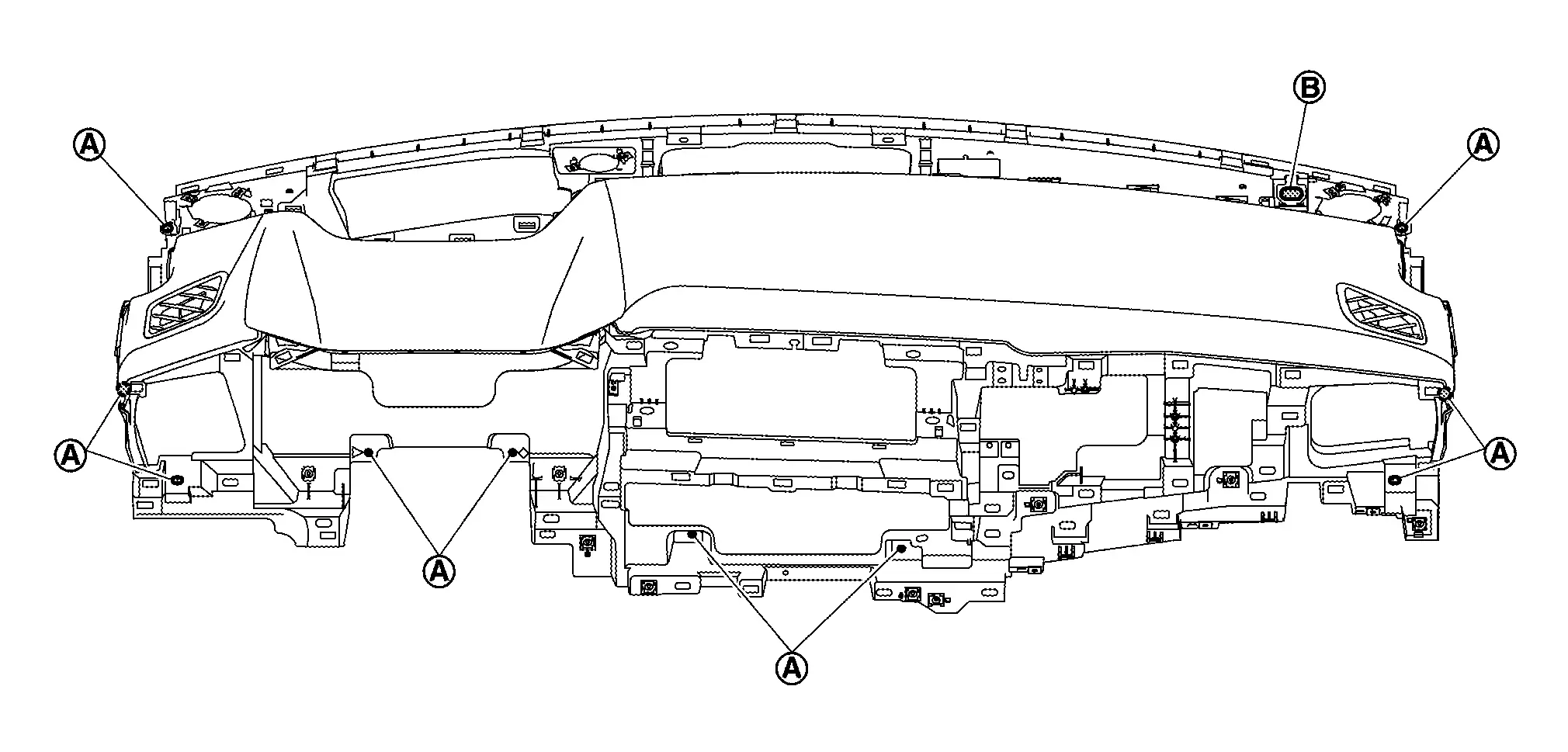
Exploded View
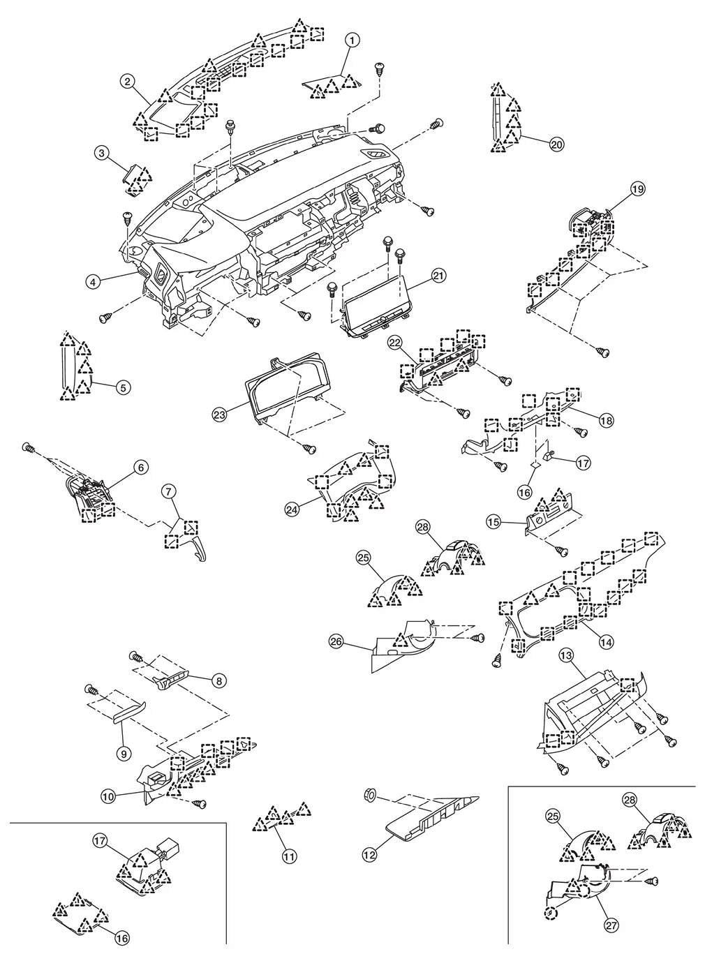
| 1. | Speaker grille RH | 2. | Instrument garnish | 3. | Speaker grille LH |
| 4. | Instrument panel assembly | 5. | Instrument mask LH | 6. | Side ventilator grille assembly LH |
| 7. | Instrument pad A | 8. | Switch bracket B | 9. | Switch bracket A |
| 10. | Instrument lower panel LH | 11. | Fuse block lid | 12. | Instrument lower cover |
| 13. | Glove box | 14. | Instrument pad B | 15. | Switch panel |
| 16. | Lamp mask [without mood lamp (instrument panel center)] | 17. | Mood lamp (instrument panel center) [with mood lamp (instrument panel center)] | 18. | Instrument lower panel center |
| 19. | Side ventilator grille assembly RH | 20. | Instrument mask RH | 21. | AV control unit |
| 22. | Center ventilator finisher | 23. | Combination meter | 24. | Cluster lid A |
| 25. | Steering column cover upper | 26. | Steering column cover lower (Japan production models) | 27. | Steering column cover lower (USA production models) |
| 28. | Steering column cover (driver monitor camera) | ||||
 |
: Pawl | ||||
 |
: Metal clip | ||||
Removal and Installation
WORK STEP
When removing instrument panel assembly, combination meter and AV control unit take steps in the order shown by the numbers below.
| PARTS | INSTRUMENT PANEL ASSEMBLY | COMBINATION METER | AV CONTROL UNIT |
|---|---|---|---|
| Center console assembly | [1] | — | — |
| Instrument mask RH | [2] | — | — |
| Glove box | [3] | — | — |
| Passenger knee air bag module | [4] | — | — |
| Instrument mask LH | [5] | — | — |
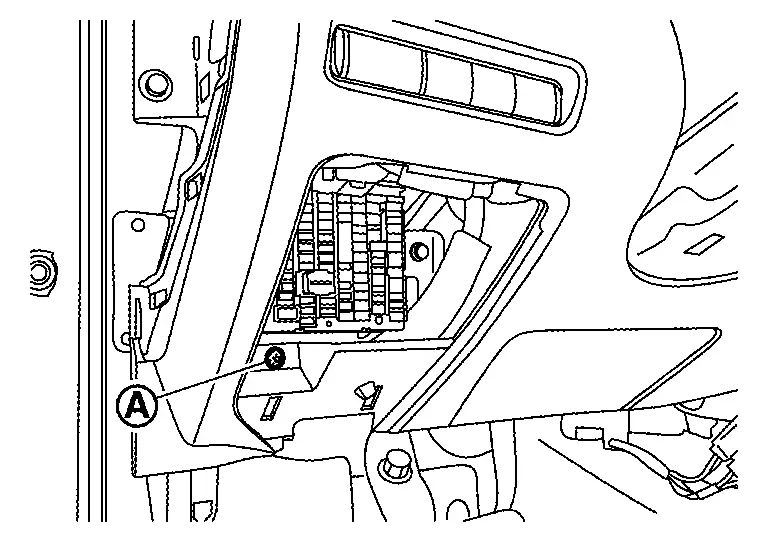
| Fuse block lid | [6] | — | — |
| Instrument lower panel LH | [7] | — | — |
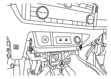
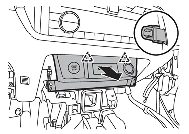
| Switch panel | [8] | — | — |
| Mood lamp (instrument panel center) [with mood lamp (instrument panel center)] | [9] | — | — |
| Lamp mask [without mood lamp (instrument panel center)] | [10] | — | — |
| Instrument lower panel center | [11] | — | — |
| Driver air bag module | [12] | — | — |
| Steering wheel | [13] | — | — |
| Steering column cover | [14] | — | — |
| Driver knee air bag module | [15] | — | — |
| Spiral cable | [16] | — | — |
| Steering angle sensor | [17] | — | — |
| Combination switch | [18] | — | — |
| Cluster lid A | [19] | [1] | [1] |
| Combination meter | [20] | [2] | — |
| Instrument pad A | [21] | — | — |
| Instrument pad B | [22] | — | [2] |
| AV control unit | [23] | — | [3] |
| Center ventilator grille and A/C switch assembly | [24] | — | — |
| Intelligent Key unit | [25] | — | — |
| Side ventilator grille assembly RH | [26] | — | — |
| Front pillar garnish (LH and RH) | [27] | — | — |
| Speaker grille LH | [28] | — | — |
| Speaker grille RH | [29] | — | — |
| Instrument panel speaker | [30] | — | — |
| Optical sensor | [31] | — | — |
| Sunload sensor (automatic air conditioner) | [32] | — | — |
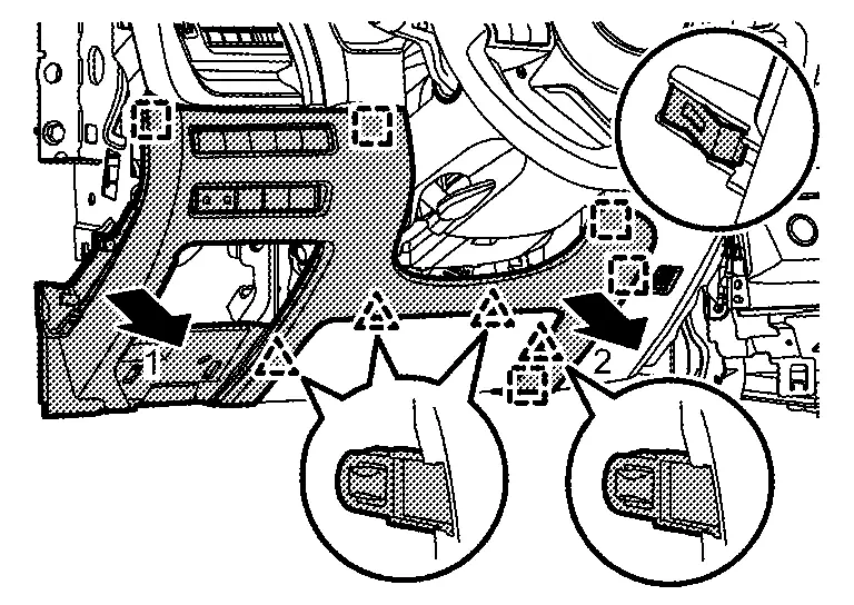
| Instrument garnish | [33] | — | — |
| Meter speaker | [34] | — | — |
| Passenger air bag module harness connector | [35] | — | — |
| Passenger air bag module mounting bolt | [36] | — | — |
| Instrument panel assembly | [37] | — | — |
[]: Number indicates step in removal procedure.
REMOVAL
WARNING:
Before servicing, ignition switch OFF, disconnect battery negative terminal and wait for 3 minutes or more.
CAUTION:
-
When removing, always use a remover tool that is made of plastic.
-
Always apply the parking brake before performing removal and installation.
Remove center console assembly. Refer to Removal and Installation.
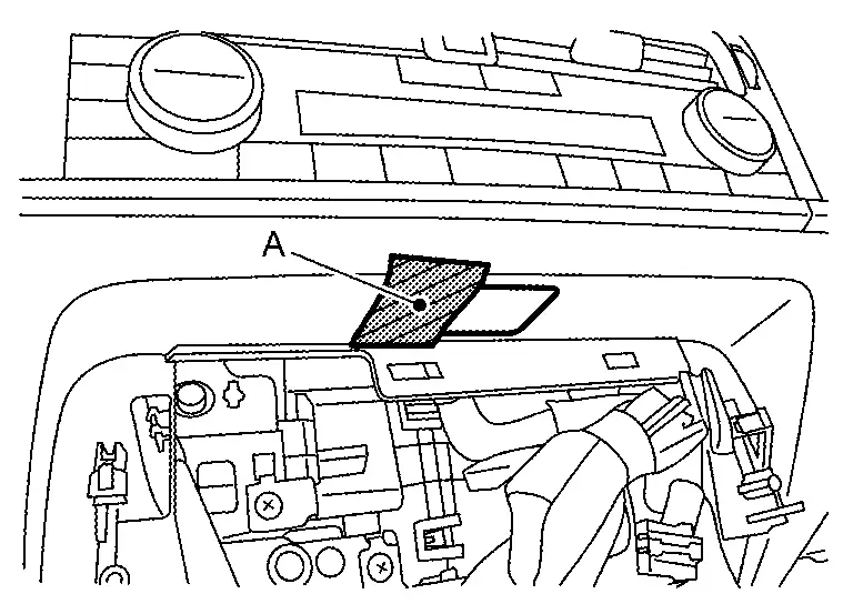
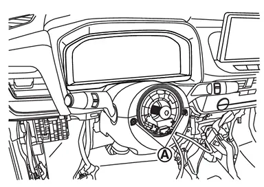
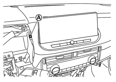
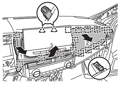
Remove instrument mask RH.Apply protective tape (A) on the part to protect it from damage.
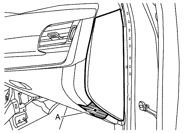
|
: Pawl |
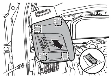
Remove glove box.Remove fixing screws (A) .
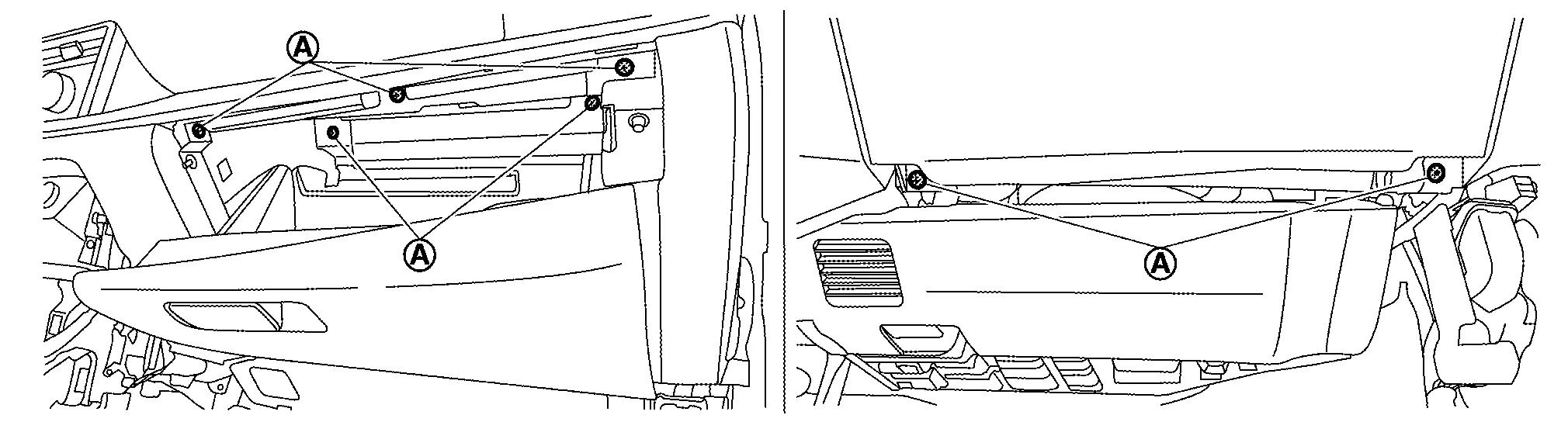
|
: Metal clip |
Remove passenger knee air bag module. Refer to Removal and Installation.
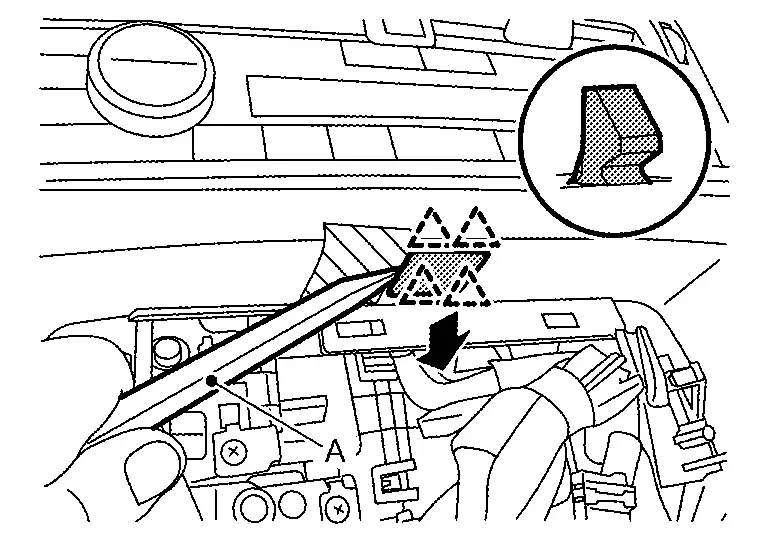
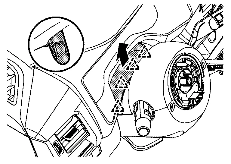
Remove instrument mask LH.Apply protective tape (A) on the part to protect it from damage.
|
: Pawl |
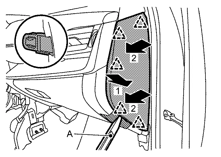
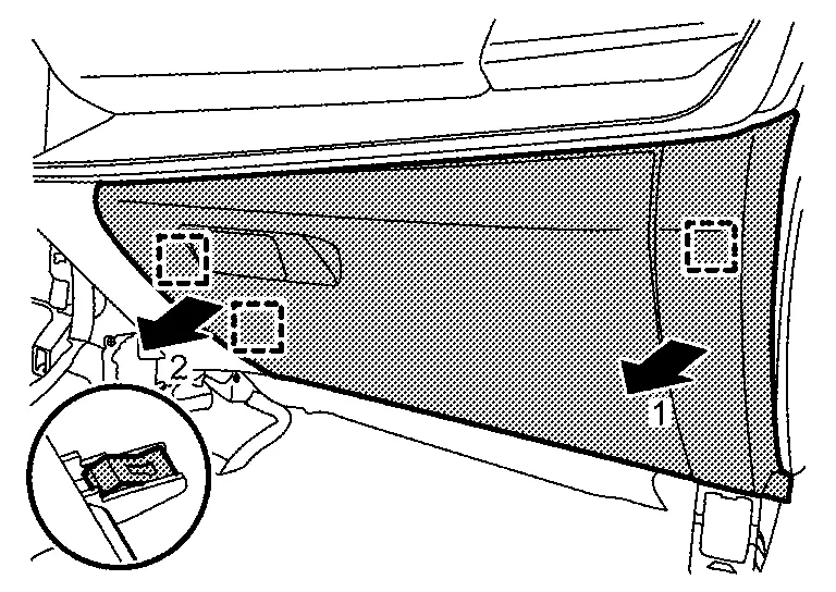
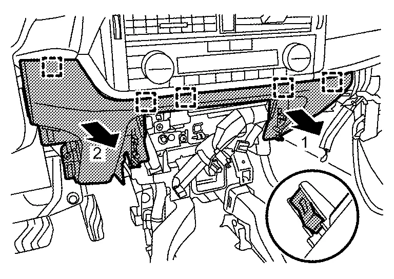
Disengage fixing pawls according to numerical order 1→2 indicated by arrows as shown in the figure, and then remove fuse block lid.
|
: Pawl |
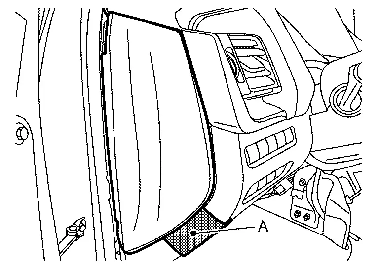
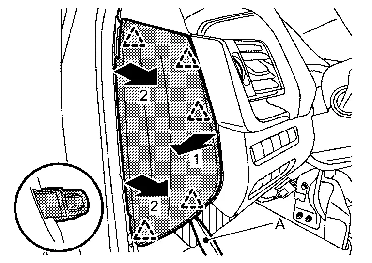
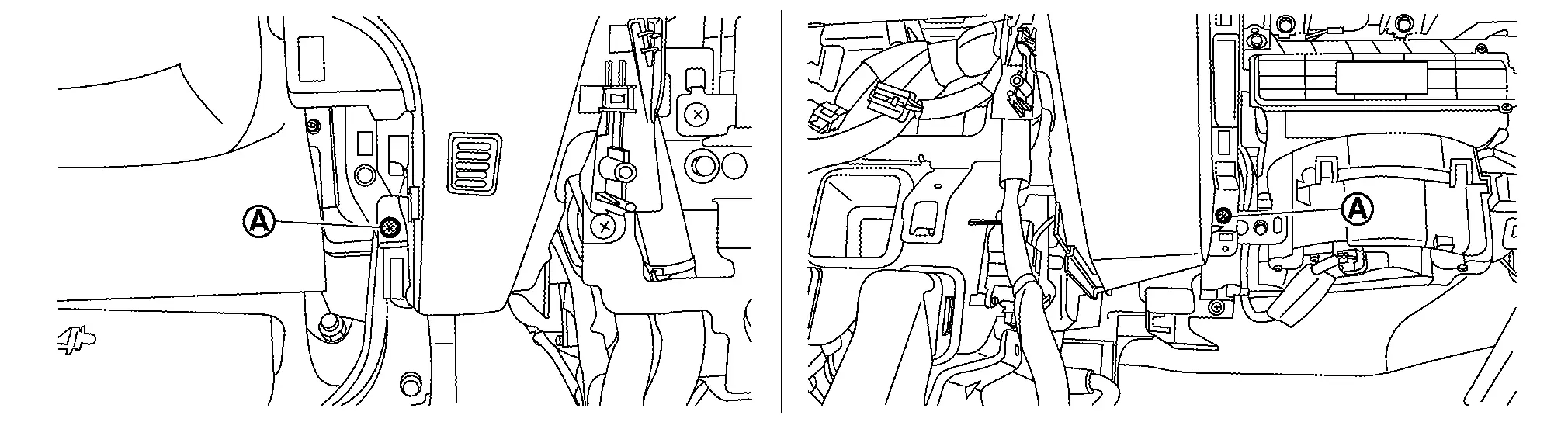
Remove instrument lower panel LH.Remove fixing screw (A).
|
: Pawl |
|
: Metal clip |
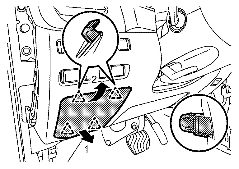
Remove switch panel.Remove fixing screws (A).
|
: Pawl |
Remove mood lamp (instrument panel center) [with mood lamp (instrument panel center)]. Refer to Removal & Installation.
Remove lamp mask [without mood lamp (instrument panel center)].Apply protective tape (A) on the part to protect it from damage.
|
: Pawl |
Remove instrument lower panel center.Remove fixing screws (A).
|
: Metal clip |
Remove driver air bag module. Refer to Removal and Installation.
Remove steering wheel. Refer to Removal and Installation.
Remove steering column cover.Disengage fixing pawls, and then remove skirt portion of cluster lid A.
|
: Pawl |
|
: Pawl |

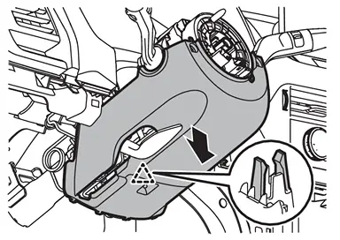
|
: Pawl |
Remove driver knee air bag module. Refer to Removal and Installation.
Remove spiral cable. Refer to Removal and Installation.
Remove steering angle sensor. Refer toRemoval and Installation.
Remove combination switch. Refer to Removal and Installation.
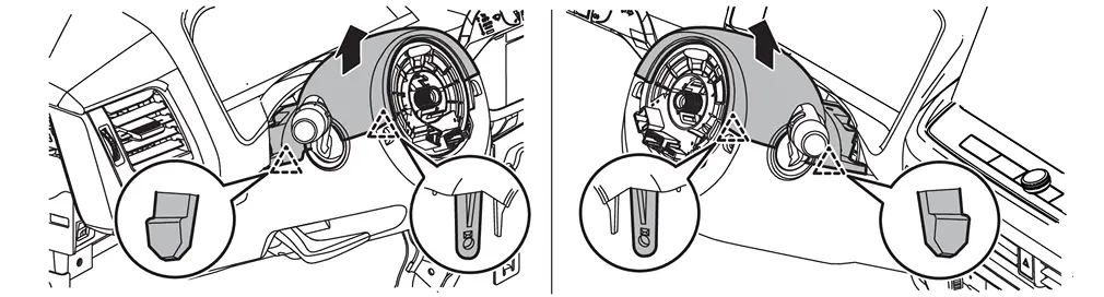
Disengage fixing pawls and metal clips according to numerical order 1→2 indicated by arrows as shown in the figure, and then remove cluster lid A.
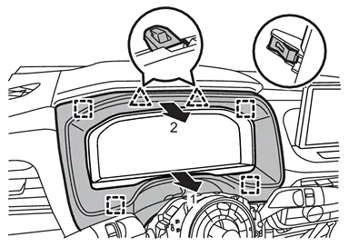
|
: Pawl |
|
: Metal clip |
 NOTE:
NOTE:
When only removing the combination meter and AV control unit, float the instrument lower panel center and instrument lower panel LH to secure a space, and then remove the cluster lid A.
Remove combination meter. Refer to the following.
-
With full TFT meter : Refer to Removal and Installation.
-
With 7 inch information display : Refer to Removal and Installation.
Remove instrument pad A.Disengage fixing metal clips, and then remove instrument pad A and side ventilator grille assembly LH as an assembly.
|
: Metal clip |
Remove instrument pad B.Remove fixing screw (A).
|
: Pawl |
|
: Metal clip |
CAUTION:
When removing instrument pad B, cover AV control unit surface with a shop cloth to prevent it from being damaged.
Remove AV control unit. Refer to Removal and Installation.
Remove center ventilator grille and A/C switch assembly.Remove fixing screws (A). Disengage fixing pawls and metal clips, and then pull out center ventilator grille and A/C switch assembly as an assembly.
|
: Pawl |
|
: Metal clip |
Remove Intelligent Key unit. Refer to Removal and Installation.
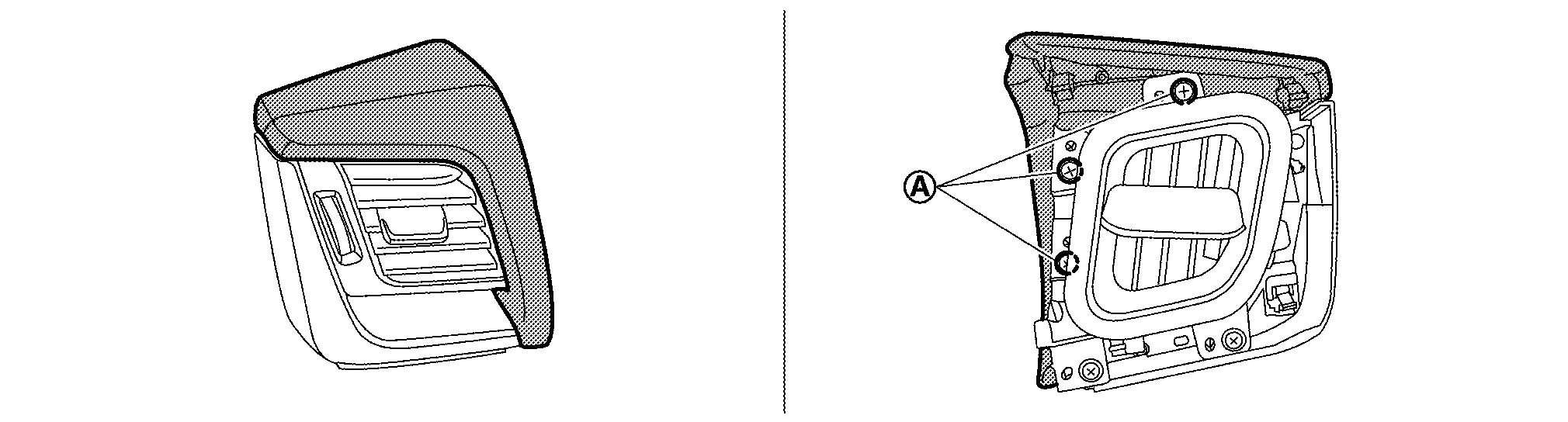
Remove side ventilator grille assembly RH.Remove fixing screws (A).
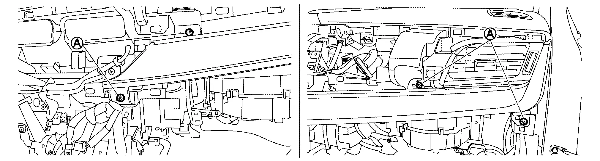
|
: Metal clip |
Remove front pillar garnish (LH and RH). Refer to Removal and Installation.
Disengage fixing pawls using a remover tool (A), and then remove speaker grille LH.

|
: Pawl |
Disengage fixing pawls using a remover tool (A), and then remove speaker grille RH.

|
: Pawl |
Remove instrument panel speaker. Refer to the following.
-
With BOSE : Refer to Removal and Installation.
-
Without BOSE : Refer to Removal and Installation.
Remove optical sensor. Refer toRemoval and Installation.
Remove sunload sensor (automatic air conditioner). Refer toRemoval and Installation.
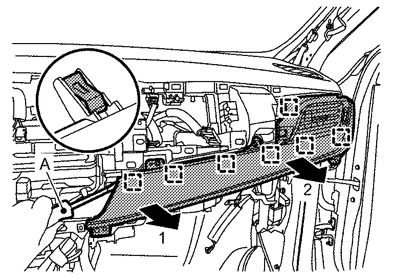
Disengage fixing pawls and metal clips, and then remove instrument garnish according to numerical order 1→2 indicated by arrows as shown in the figure.
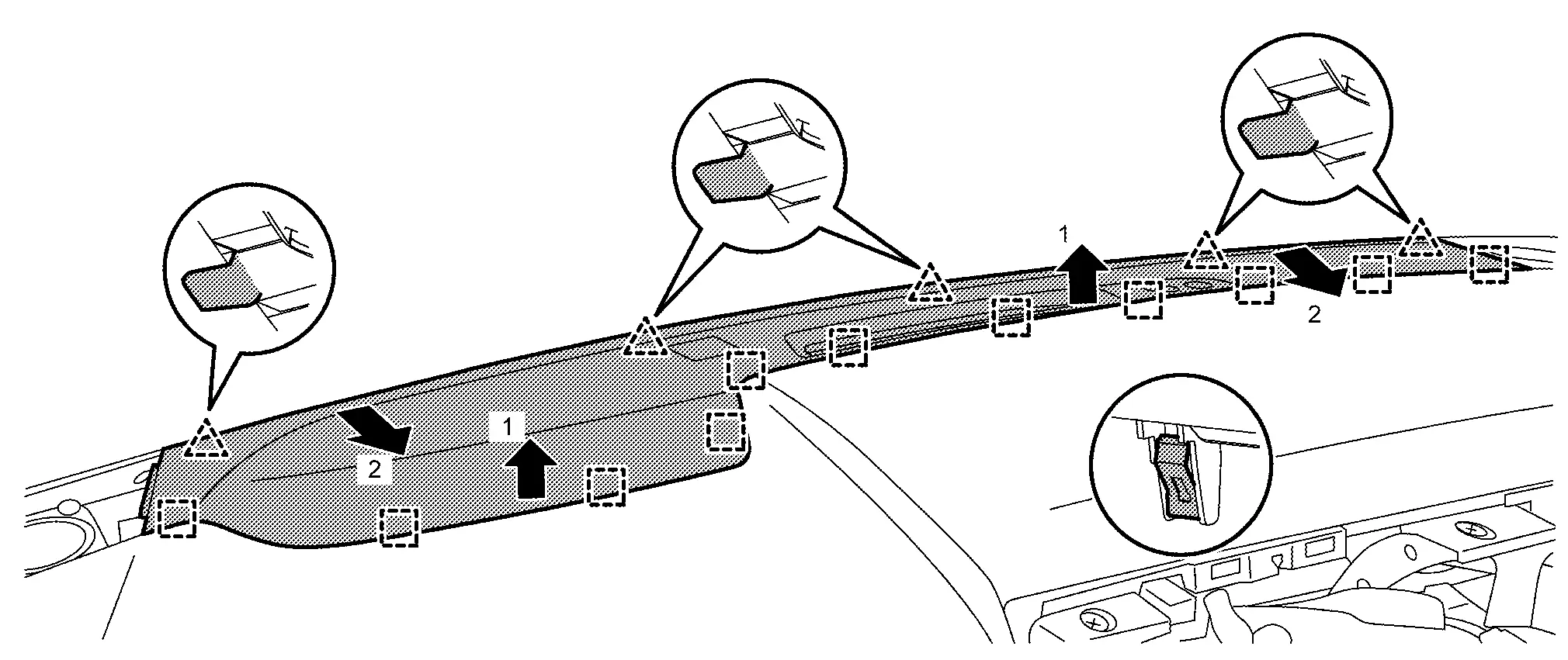
|
: Pawl |
|
: Metal clip |
Remove meter speaker (with 7 inch information display). Refer to Removal and Installation.
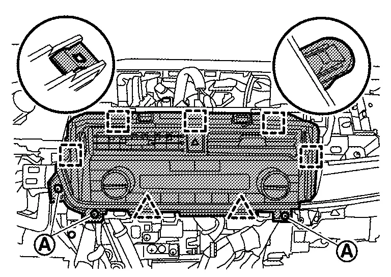
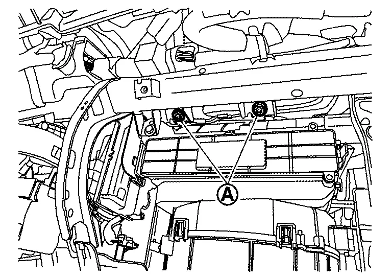
Disconnect passenger air bag module harness connectors (A).
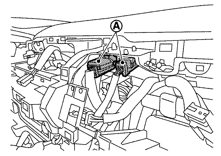
Remove passenger air bag module mounting bolts (A).
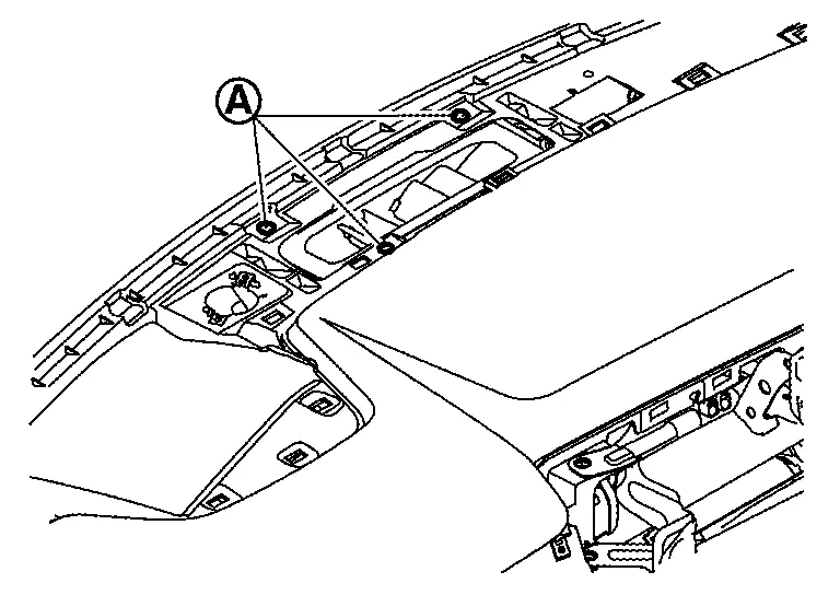
Remove instrument panel assembly.Disengage fixing clips (A) .
CAUTION:
When removing instrument panel assembly, 2 workers are required to prevent it from dropping.
Remove the following parts after removing instrument panel assembly.
-
Passenger air bag module : Refer to Removal and Installation.
-
Side defroster grille (LH and RH) : Refer to Removal and Installation.
-
Side defroster nozzle (LH and RH) : Refer to Removal and Installation.
-
Telematics antenna (with telematics system) : Refer to Removal & Installation.
INSTALLATION
Installation is in the reverse order of removal.
CAUTION:
-
Never use the steering wheel mounting bolt after removal, replace with the new bolt.
-
Never use the passenger air bag module mounting bolts after removal, replace with the new bolts.
Other materials:
Symptom Diagnosis. Intelligent Key Interlock Function Does Not Operate
Diagnosis Procedure
CHECK VEHICLE SPECIFICATION
Check if vehicle equipped navigation system.
Is equipped navigation system?
YES>>
GO TO 2.
NO>>
GO TO 3.
CHECK LOG-IN FUNCTION
Check log-in function. Refer to System Description.
Is the inspection result normal?
YES>>
G ...
Evtc Branch Line Circuit
Diagnosis Procedure
CHECK CONNECTOR
Turn the ignition switch OFF.
Disconnect the battery cable from the negative terminal.
Check the terminals and connectors of the electric intake valve
timing control module for damage, bend and loose connection (unit side
and connector side).
...
P06db Engine Oil Pressure Control Solenoid Valve
DTC Description
DTC DETECTION LOGIC DTC
CONSULT screen terms
(Trouble diagnosis content)
DTC detection condition
P06DB
00
ENGINE OIL PRESSURE CONTROL
(Engine oil pressure control circuit low)
Diagnosis condition
—
Signal (terminal)
Engine oil pressure control so ...