
Nissan Rogue (T33) 2021-Present Service Manual: Removal and Installation :: Roof Side Molding
Exploded View
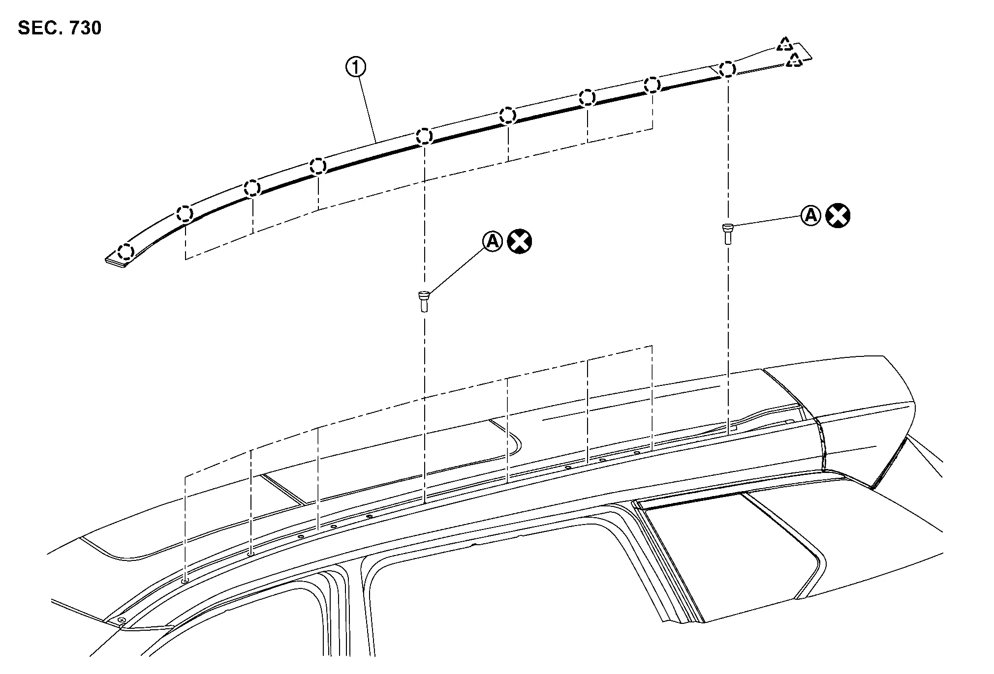
 |
Roof side molding | ||||
 |
: Rivet | ||||
 |
: Clip | ||||
 |
: Pawl | ||||
 |
: Always replace after every disassembly. | ||||
Removal and Installation
REMOVAL
 NOTE:
NOTE:
Without Rock Creek® shown, with Rock Creek® similar.
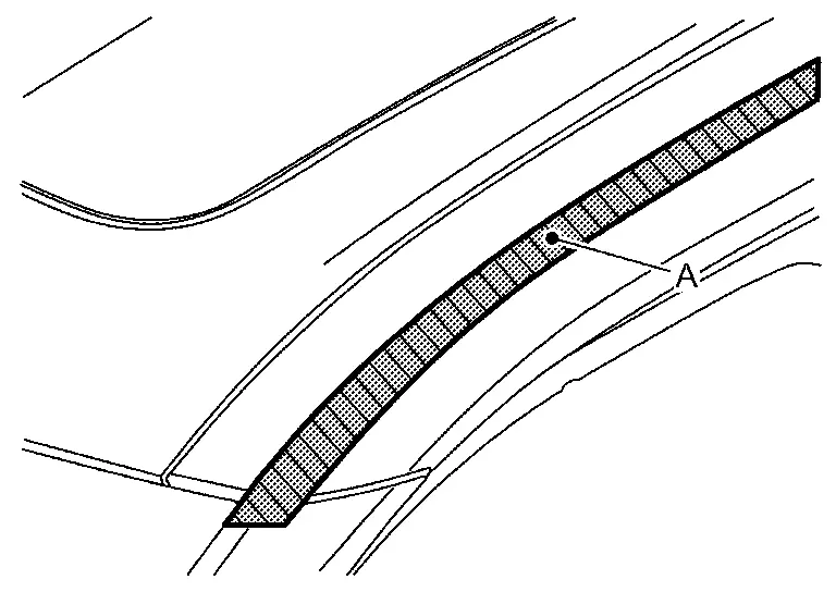
Apply protective tape (A) on the part to protect it from damage.
Disengage roof side molding fixing clips using a remover tool (A).
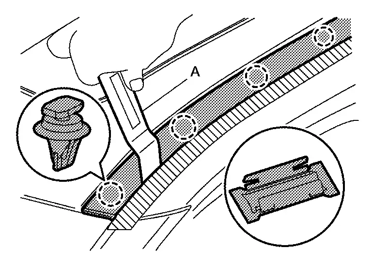
|
: Clip |
Remove roof side molding fixing pawls, and then remove roof side molding.
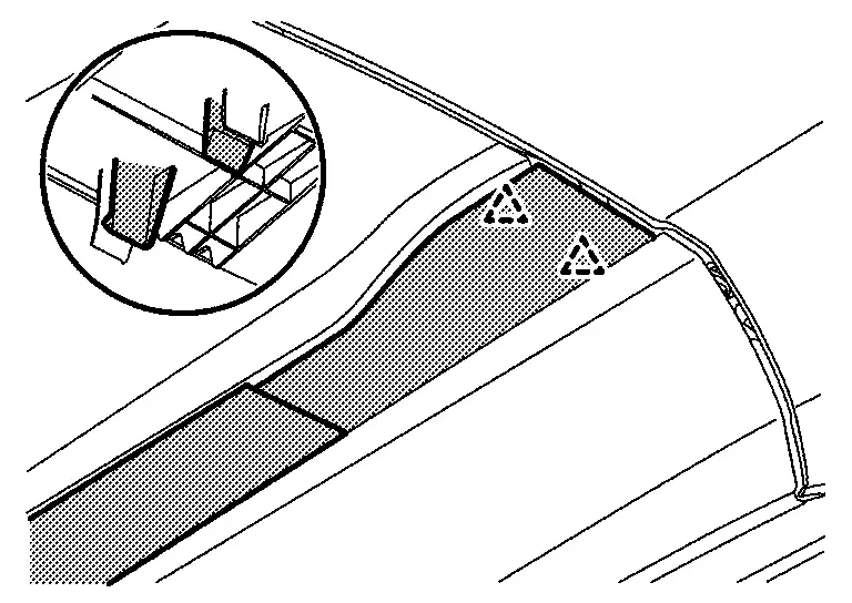
|
: Pawl |
Remove any roof rail clips (A) that may have detached from the roof rail, and then reattach them to the roof rail.
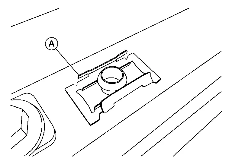
Remove roof side molding rivet.
NOTE:
Grind the head of rivet with a drill (B) [bit of φ4.7 −φ4.9 mm (φ0.185 −φ0.193 in)].
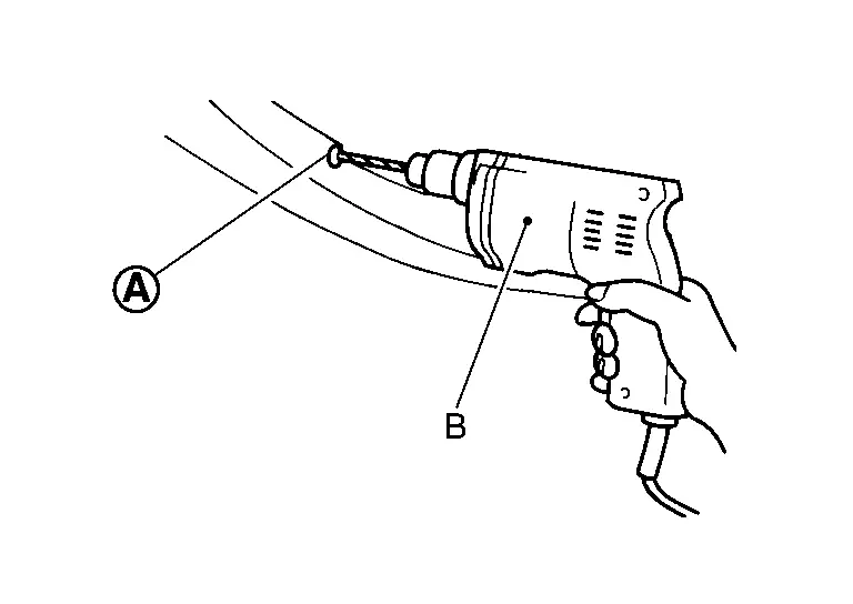
INSTALLATION
Securely crimp roof rail rivet with a hand riveter (A).
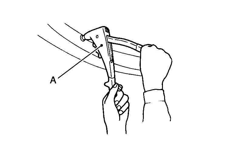
Inspect roof rail clips still attached to the roof rail, and confirm that they are completely seated. Seat the roof rail clips as needed.
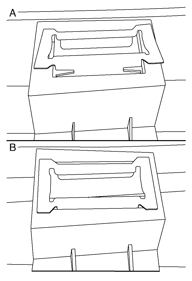
| (A) | : Partially seated |
| (B) | : Fully seated |
Using suitable tool (A), remove any sealer and any remaining pieces of the roof rail clip that are present from the leading roof rail clip hole.
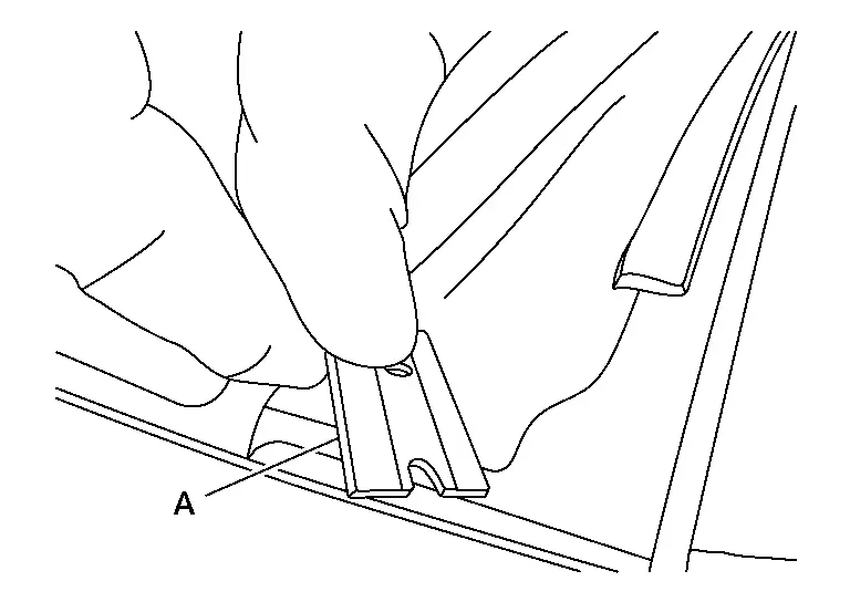
NOTE:
-
Remove any remaining sealer with isopropyl alcohol.
-
Ensure that the paint is not damaged. If paint damage occurs, follow NISSAN paint guidelines.
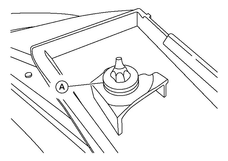
Replace roof rail clip, and remove seal (A) from roof rail clip.
Apply a small bead of silicone sealer around hole (A).
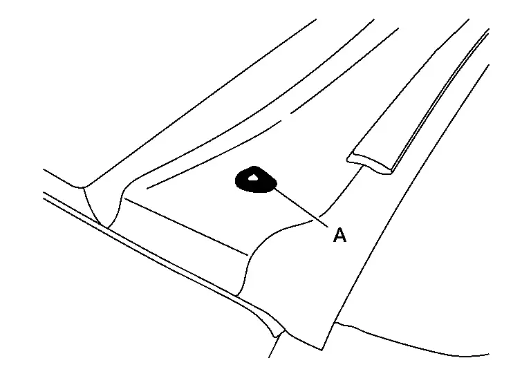
Install the roof rail.
Other materials:
P12a8 Cruise Control
DTC Description
DTC DETECTION LOGIC DTC
CONSULT screen terms
(Trouble diagnosis content) DTC detecting condition
P12A8
00
Cruise control communication
(Cruise control)
Diagnosis condition
Ignition switch ON
Signal
CAN communication signal
Threshold
Abnormal driv ...
U0073-00 Control Module Comm Bus a Off
DTC Description
DTC DETECTION LOGIC DTC No.
CONSULT screen terms
(Trouble diagnosis content) DTC detection condition
U0073
00
Control module comm Bus A Off
(Control module communication Bus A Off)
1
Diagnosis condition
When ignition switch is ON.
When the power sup ...
C1220-54 Incomplete Air Bleeding
DTC Description
DTC DETECTION LOGIC DTC
CONSULT screen terms
(Trouble diagnosis content) DTC detecting condition
C1220-54
INCOMP AIR BLEEDING
(Incomplete air bleeding)
Diagnosis condition
Ignition switch: ON
Signal
—
Threshold
Air bleeding of electro-hydraulic co ...