Nissan Rogue (T33) 2021-Present Service Manual: Removal and Installation :: Rear Bumper
Exploded View
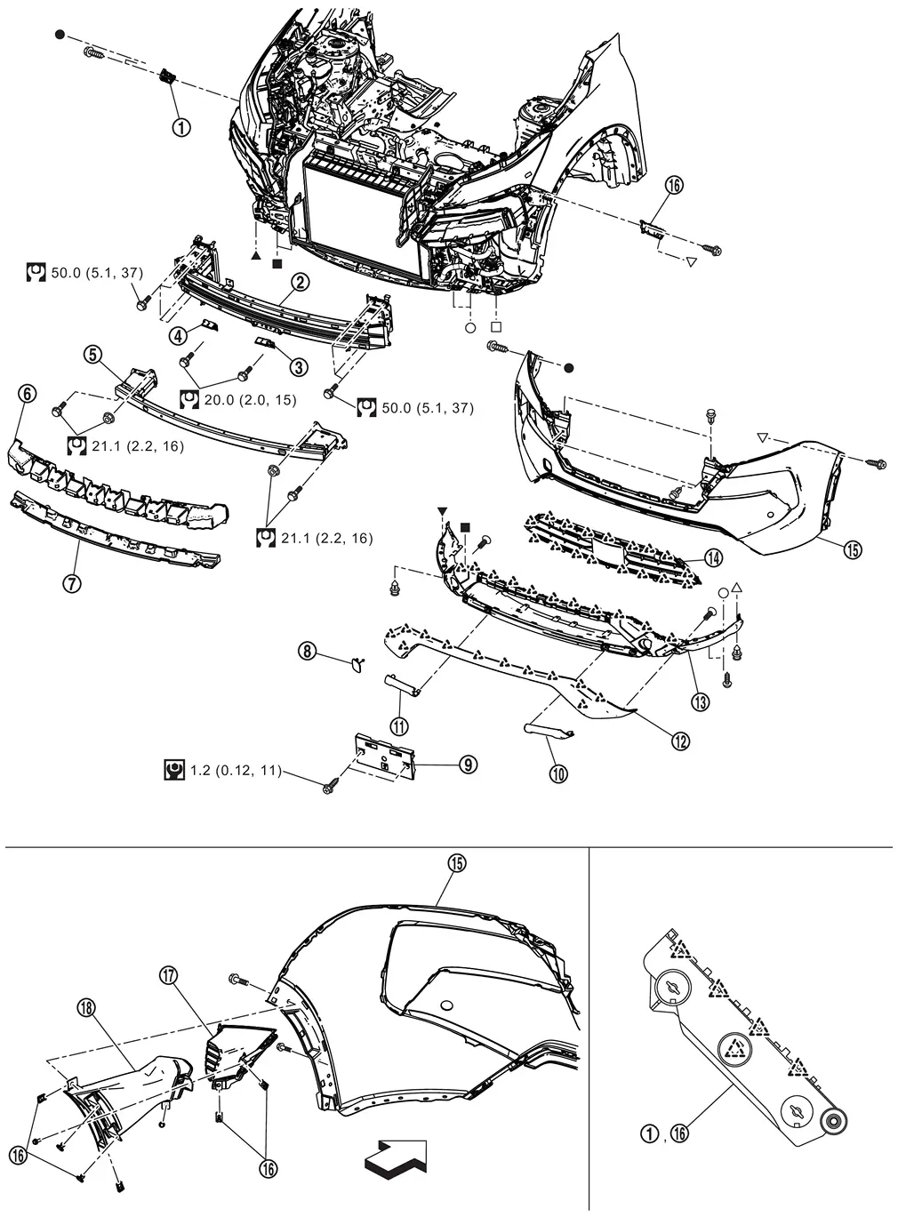
| 1. | Rear bumper side bracket LH | 2. | Grommet | 3. | Rear bumper fascia RH |
| 4. | Rear bumper fascia LH | 5. | Rear bumper fascia trim LH | 6. | Rear bumper fascia trim RH |
| 7. | Rear bumper fascia | 8. | Rear bumper finisher | 9. | Rear bumper molding (if equipped) |
| 10. | Rear bumper cover | 11. | Reflex reflector LH | 12. | Reflex reflector RH |
| 13. | Rear bumper reinforcement | 14. | Rear bumper stay RH | 15. | Rear bumper side bracket RH |
| 16. | Rear bumper stay LH | 17. | Spring nut | 18. | Rear bumper bracket (if equipped) |
| 19. | Bumper clip (if equipped) | ŌĆö | ŌĆö | ||
 |
: Pawl | ||||
 |
: Always replace after every disassembly. | ||||
 |
: N┬Ęm (kg-m, ft-lb) | ||||
 , ,  , ,  , ,  , ,  , ,  , ,  , ,  , ,  : Indicates that the part is connected at points with same symbol in actual Nissan Ariya vehicle. : Indicates that the part is connected at points with same symbol in actual Nissan Ariya vehicle. |
|||||
Removal and Installation
CAUTION:
Bumper fascia is made of resin. Never apply strong force to it, and be careful to prevent contact with oil.
REMOVAL
Fully open back door.
Remove rear combination lamp (body side). Refer to Removal and Installation.
Remove rear fillet molding rear. Refer to Removal and Installation.
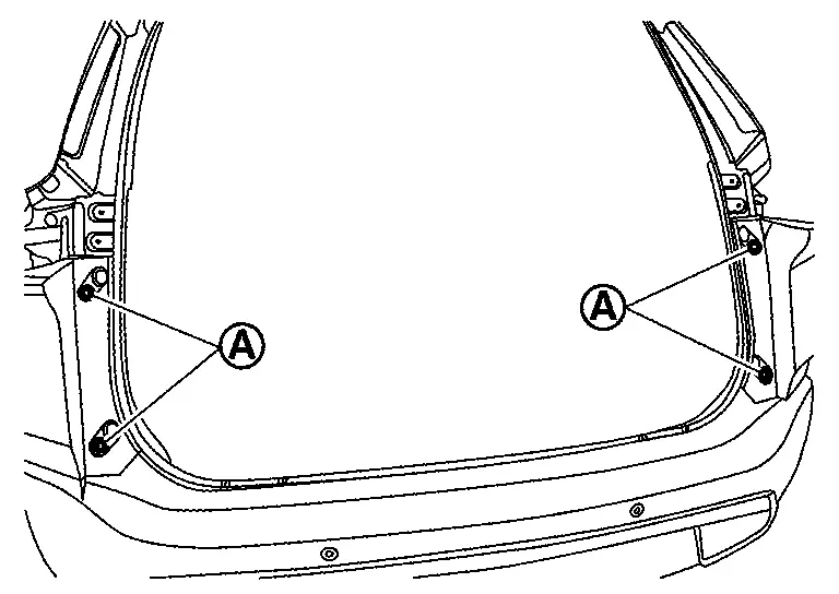
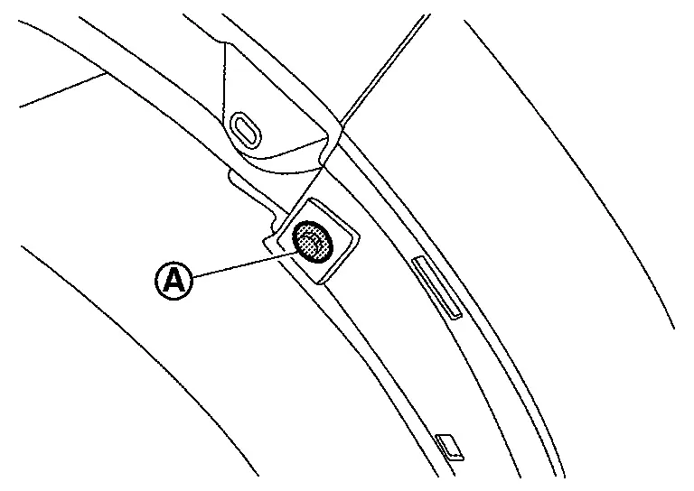
Remove rear bumper fascia fixing screws (A).
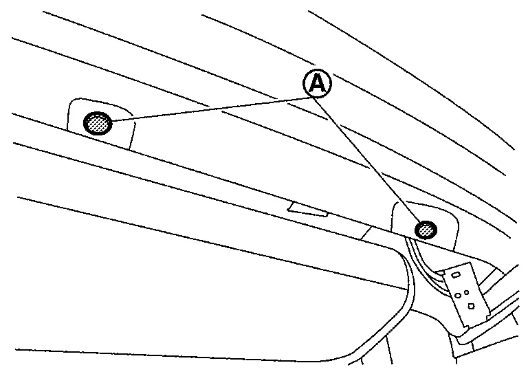
Remove rear bumper fascia fixing clips (A).
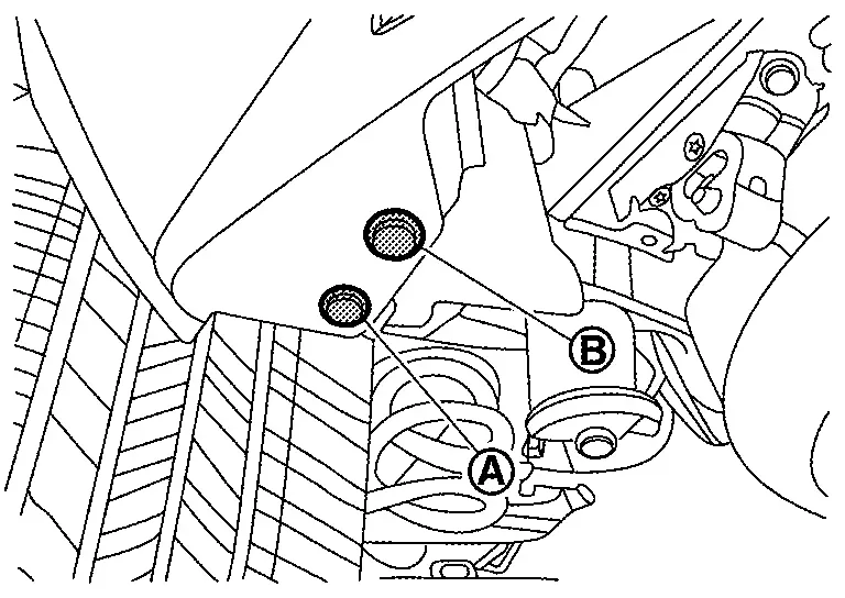
Remove rear bumper fascia mounting bolt (A) and fixing clip (B).
Remove rear bumper fascia fixing screw (A).
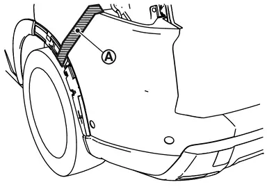
Apply protective tape (A) on the part to protect it from damage.
Pull rear bumper fascia side toward the Nissan Ariya vehicle side to disengage the fitting of rear bumper side bracket and rear bumper fascia side according to the numerical order 1ŌåÆ2 as shown by the arrows in the figure.
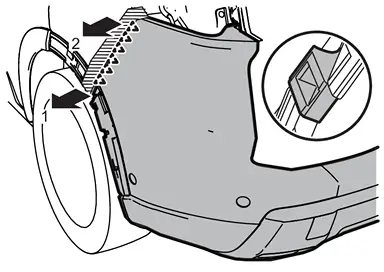
CAUTION:
When removing rear bumper fascia, 2 workers are required so as to prevent it from dropping.
|
: Pawl |
Disconnect harness connectors.
Remove rear bumper fascia.
CAUTION:
When removing rear bumper fascia, 2 workers are required so as to prevent it from dropping.
Remove the following parts after removing rear bumper fascia.
-
Hands free sensor control unit (if equipped). Refer to Removal and Installation.
-
Rear sonar sensor. Refer to Removal and Installation.
-
Rear side radar. Refer toRemoval and Installation.
-
Reflex reflector. Refer to Removal and Installation.
-
Rear bumper bracket
-
Rear bumper fascia LH and RH
-
Rear bumper finisher
-
Rear bumper molding
-
Rear bumper cover
Remove rear bumper side bracket fixing screws and pawl, and then remove rear bumper side bracket.
Remove rear bumper reinforcement mounting nuts, and then remove rear bumper reinforcement.
Remove rear bumper stay mounting bolts, and then remove rear bumper stay.
INSTALLATION
Installation is in the reverse order of removal.
 NOTE:
NOTE:
-
The following table shows the specified values for checking normal installation status.
-
Fitting adjustment cannot be performed.
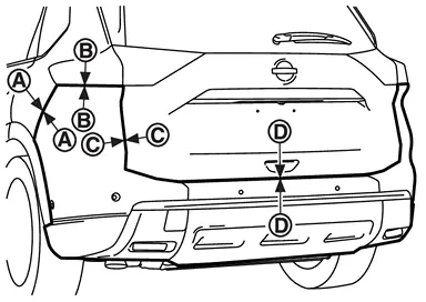
Portion Clearance Surface height difference Rear bumper fascia ŌĆō Body side outer panel A
ŌĆō
A0.1 ŌĆō 1.3 mm
(0.004 ŌĆō 0.051 in)(ŌłÆ1.7) ŌĆō (+0.3) mm
[(ŌłÆ0.067) ŌĆō (+0.012) in]Rear bumper fascia ŌĆō Rear combination lamp (body side) B
ŌĆō
B0.1 ŌĆō 3.9 mm
(0.004 ŌĆō 0.154 in)(ŌłÆ2.5) ŌĆō (+1.3) mm
[(ŌłÆ0.098) ŌĆō (+0.051) in]Rear bumper fascia ŌĆō Back door panel C
ŌĆō
C2.6 ŌĆō 6.8 mm
(0.102 ŌĆō 0.268 in)(ŌłÆ4.4) ŌĆō (+0.2) mm
[(ŌłÆ0.173) ŌĆō (+0.008) in]D
ŌĆō
D5.4 ŌĆō 9.8 mm
(0.213 ŌĆō 0.386 in)ŌĆö -
After installation, perform side radar alignment. Refer to Work Procedure.
Other materials:
C1f48-16 Abs/tcs/vdc System
Without Propilot Assist 2.1
DTC Description
DTC DETECTION LOGIC DTC
CONSULT screen terms
(Trouble diagnosis content) DTC detection condition
C1F48
16
ABS/TCS/VDC CIRC
(Anti-lock braking system/Traction control system/Nissan Ariya Vehicle dynamics control system circuit)
...
Basic Inspection. Diagnosis and Repair Work Flow
Work Flow
OVERALL SEQUENCEDETAILED FLOWINTERVIEW FROM THE CUSTOMER
Clarify customer complaints before inspection. To do so, reproduce
the symptom before hand and fully understand it. Then interview the
customer thoroughly. Check the symptoms by driving Nissan Ariya vehicle
with the customer, ...
Symptom Diagnosis. Electric Power Steering Warning Lamp Does Not Turn on
Description
The power steering warning lamp does not illuminate when the ignition switch is ON (lamp check).
Diagnosis Procedure
CHECK THE POWER STEERING WARNING LAMP
Perform trouble diagnosis for the power steering warning lamp system. Refer toComponent Function Check .
Is the inspection resul ...