Nissan Rogue (T33) 2021-Present Service Manual: Removal and Installation :: Front Grille
Exploded View
WITHOUT ROCK CREEKÂŪ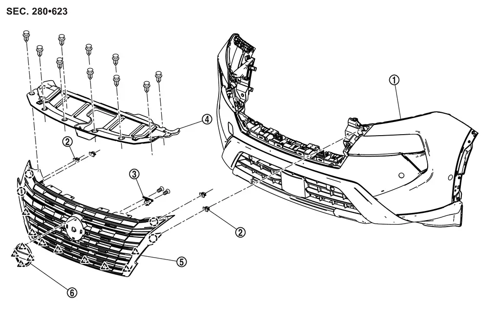
| 1. | Front bumper fascia | 2. | Grommet | 3. | Front camera (if equipped) |
| 4. | Front grille cover | 5. | Front grille | 6. | Front emblem |
 |
: Clip | ||||
 |
: Pawl | ||||
WITH ROCK CREEKÂŪ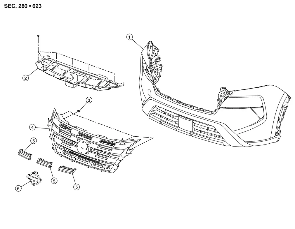
| 1. | Front bumper fascia | 2. | Front grille cover | 3. | Grommet |
| 4. | Front grille | 5. | Front grille inserts | 6. | Front emblem |
|
: Clip | ||||
|
: Pawl | ||||
Removal and Installation
REMOVAL
Fully open hood assembly.
Remove license plate bracket fixing screws, and then remove license plate bracket.
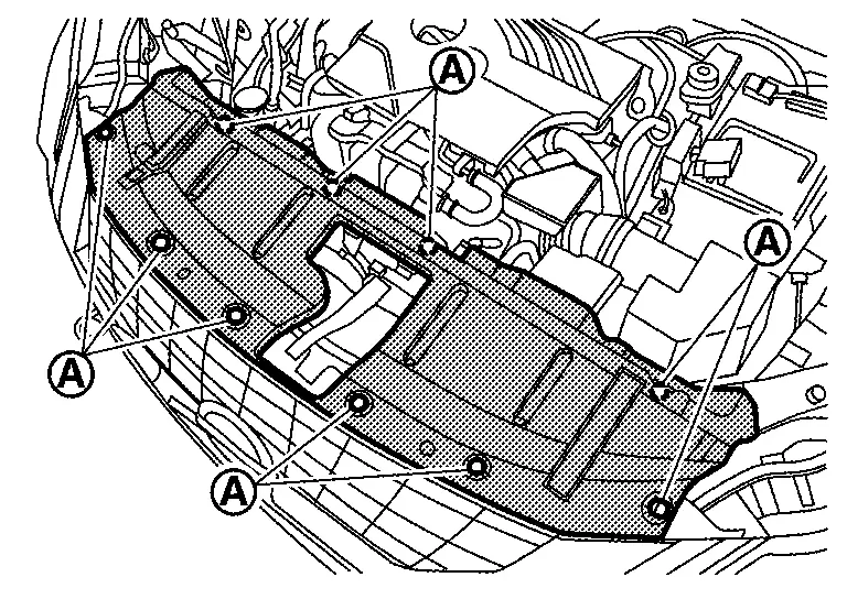
Remove front grille cover fixing clips  , and then remove front grille cover.
Disengage front grille fixing clips and pawls from back side while pulling front grille toward Nissan Ariya vehicle front.
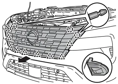
|
: Clip |
|
: Pawl |
Disconnect front camera harness connector. (if so equipped)
Remove front grille.
Remove the following parts after removing front grille.
-
Front camera (if so equipped). Refer to Removal and Installation.
-
Front emblem
INSTALLATION
Installation in the reverse order of removal.
If equipped with front camera, perform camera image calibration. Refer to Work Procedure (WITHOUT ProPILOT Assist 2.1) or Work Procedure (WITH ProPILOT Assist 2.1).
CAUTION:
Perform the calibration and perform the writing to the around view monitor control unit when removing and replacing each camera, removing the camera mounting parts (front grille, door mirror, etc.) and replacing the around view monitor control unit.
Other materials:
Admission Valve
Exploded View
Air duct bracket
Admission valve
gasket
Air duct hose
Air duct
Comply with the installation procedure when tightening. Refer to Removal and Installation.
To air duct. Refer to Exploded View.
To turbocharger. Refer to Exploded V ...
SystÃĻme 4x4 Intelligent
En cas de dysfonctionnement du systÃĻme 4x4 Intelligent du Nissan Rogue alors que le moteur est en marche, diffÃĐrents messages d'avertissement peuvent s'afficher sur l'ÃĐcran d'informations du vÃĐhicule afin d'informer le conducteur de l'ÃĐtat du systÃĻme de transmission intÃĐgrale.
Si l'a ...
Distance Sensor Inspection
Work Procedure
CAUTION:
In the following conditions, the distance sensor may not perform optimally.
Attaching stickers or installing aftermarket parts around the distance sensor.
Repairs performed by the customer.
Scratches, bird droppings, insects, mud, etc., around the distance se ...