Nissan Rogue (T33) 2021-Present Service Manual: Removal and Installation :: Front Bumper
Exploded View
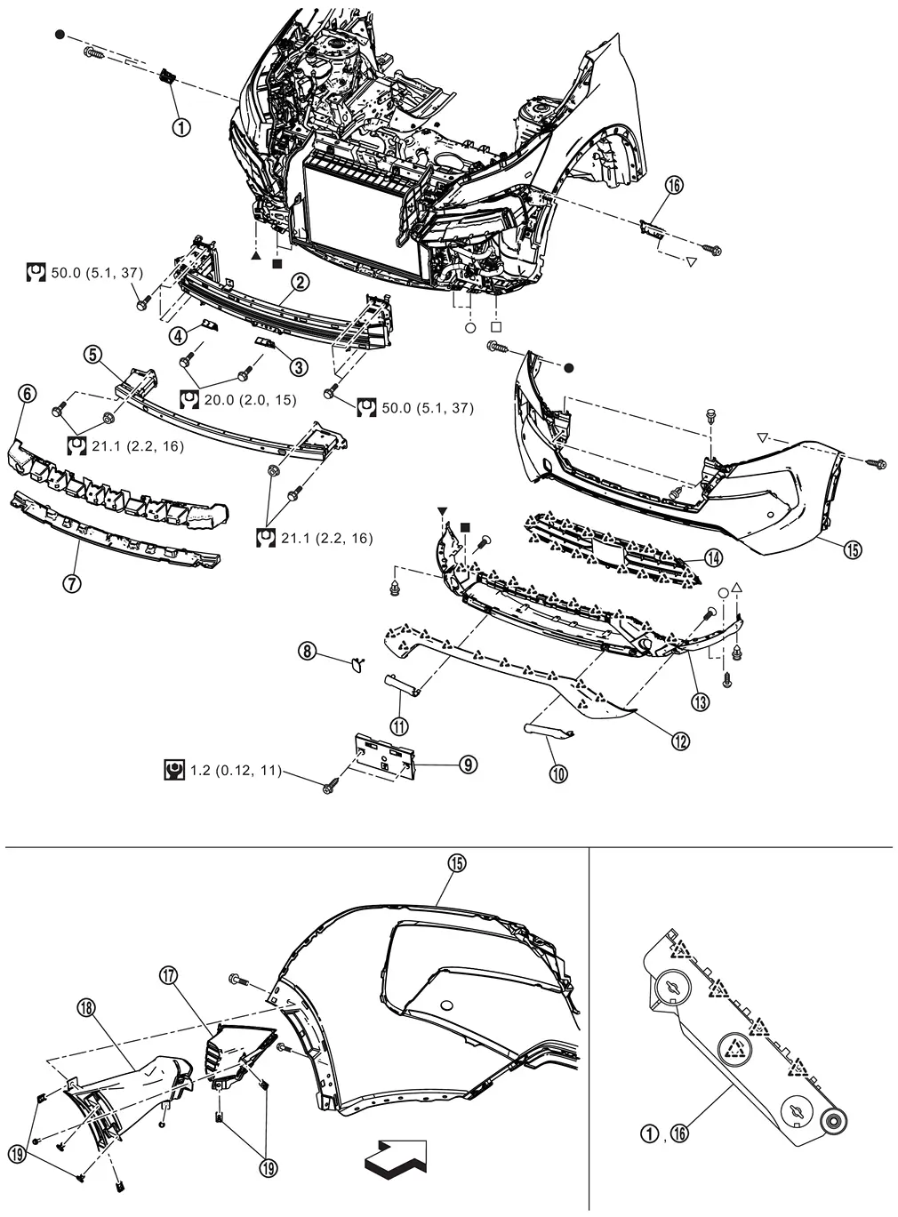
| 1. | Front bumper side bracket RH | 2. | Front bumper reinforcement | 3. | Front bumper reinforcement bracket LH |
| 4. | Front bumper reinforcement bracket RH | 5. | Front bumper reinforcement lower | 6. | Front bumper energy absorber |
| 7. | Front bumper energy absorber lower | 8. | Bumper bracket cover | 9. | License plate bracket |
| 10. | Front bumper finisher LH | 11. | Front bumper finisher RH | 12. | Front bumper molding |
| 13. | Front bumper molding lower | 14. | Front bumper grille | 15. | Front bumper fascia |
| 16. | Front bumper side bracket LH | 17. | Front bumper finisher | 18. | Front bumper bracket |
| 19. | Spring nut | ŌĆö | ŌĆö | ŌĆö | ŌĆö |
 |
: Pawl | ||||
| : Nissan Ariya Vehicle front | |||||
 |
: N┬Ęm (kg-m, in-lb) | ||||
 |
: N┬Ęm (kg-m, ft-lb) | ||||
 , ,  , ,  , ,  , ,  , ,  , ,  , ,  , ,  : Indicates that the part is connected at points with same symbol in actual Nissan Ariya vehicle. : Indicates that the part is connected at points with same symbol in actual Nissan Ariya vehicle. |
|||||
Removal and Installation
CAUTION:
Front bumper fascia is made of resin. Never apply strong force to it, and be careful to prevent contact with oil.
REMOVAL
Remove front grille. Refer to Removal and Installation.
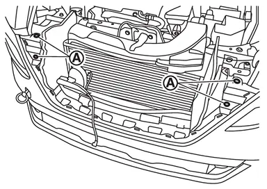
Remove front bumper fascia fixing clips (A).
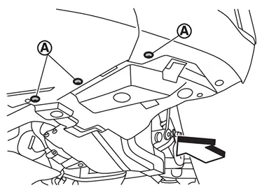
Remove engine under cover front fixing clips (A).
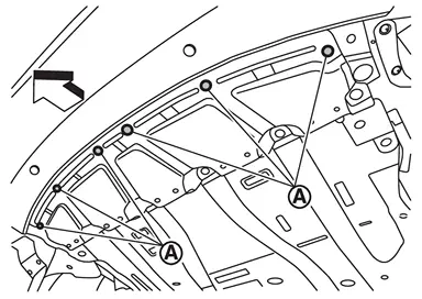
| : Nissan Ariya Vehicle front |
Remove front spoiler fixing screws (A) and clip (B), and then remove front spoiler.
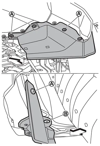
| : Nissan Ariya Vehicle front |
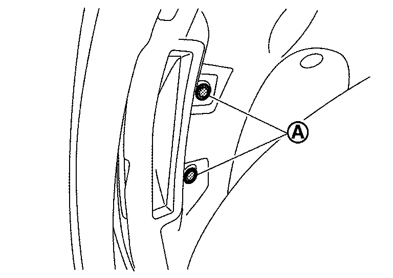
Remove front bumper fascia fixing screws (A).
| : Nissan Ariya Vehicle front |
Remove front side of front fillet molding (LH and RH). Refer to Removal and Installation.
Remove front bumper bracket fixing clips (A) inside of fender protector.
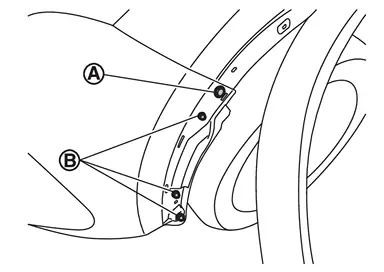
Remove front bumper fascia fixing screw (A) and bolts (B).
Apply protective tapes (A) on the part to protect it from damage.
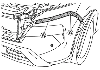
Pull front bumper fascia side toward the Nissan Ariya vehicle side to disengage the fitting of front bumper side bracket and front bumper fascia side according to the numerical order 1ŌåÆ2 as shown by the arrows in the figure.
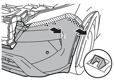
CAUTION:
When removing front bumper fascia, 2 workers are required so as to prevent it from dropping.
|
: Pawl |
Disconnect front sonar sensor harness connector (if so equipped).
Disconnect front side radar harness connectors (if so equipped).
Remove front bumper fascia.
CAUTION:
When removing front bumper fascia, 2 workers are required so as to prevent it from dropping.
Remove the following parts after removing front bumper fascia.
-
Front sonar sensor (if so equipped). Refer to Removal and Installation.
-
Side radar (if so equipped). Refer toRemoval and Installation.
-
Front bumper bracket
-
Front bumper finisher
-
Front bumper grille
-
Front bumper molding
-
Front bumper molding lower
-
Bumper bracket cover
Remove front bumper energy absorber and front bumper energy absorber lower.
Remove active grille shutter. Refer to Removal and Installation.
Remove front bumper reinforcement.
-
Remove harness clips.
-
Remove head lamp. Refer to Removal and Installation.
-
Remove horn. Refer to Removal and Installation.
-
Remove distance sensor. Refer to Removal and Installation.
-
Remove front bumper reinforcement mounting bolts, and then remove front bumper reinforcement.
-
Remove front bumper reinforcement bracket mounting bolt, and then remove front bumper reinforcement bracket.
Remove front bumper reinforcement lower mounting bolts and nuts, and then remove front bumper reinforcement lower.
Remove front bumper side bracket fixing screws and pawl, and then remove front bumper side bracket.
INSTALLATION
Installation is in the reverse order of removal.
 NOTE:
NOTE:
-
The following table shows the specified values for checking normal installation status.
-
Fitting adjustment cannot be performed.
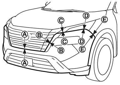
| Portion | Clearance | Surface height difference | |
|---|---|---|---|
| Front bumper fascia ŌĆō Front grille |
A ŌĆō A |
0.2 ŌĆō 2.8 mm (0.008 ŌĆō 0.110 in) |
ŌĆö |
|
B ŌĆō B |
0.5 ŌĆō 4.1 mm (0.020 ŌĆō 0.161 in) |
0.3 ŌĆō 3.5 mm (0.012 ŌĆō 0.138 in) |
|
| Front bumper fascia ŌĆō Front combination lamp |
C ŌĆō C |
0.3 ŌĆō 3.1 mm (0.012 ŌĆō 0.122 in) |
0.8 ŌĆō 3.6 mm (0.031 ŌĆō 0.142 in) |
|
D ŌĆō D |
0.2 ŌĆō 3.4 mm (0.008 ŌĆō 0.134 in) |
(ŌĆō0.1) ŌĆō (+3.1) mm [(ŌĆō0.004) ŌĆō (+0.122) in] |
|
| Front bumper fascia ŌĆō Front fender assembly |
E ŌĆō E |
0.3 ŌĆō 1.3 mm (0.012 ŌĆō 0.051 in) |
(ŌłÆ2.0) ŌĆō (0.0) mm [(ŌłÆ0.079) ŌĆō (0.000) in] |
Other materials:
P2096 A/f Sensor 1
DTC Description
DTC DETECTION LOGIC DTC
CONSULT screen terms
(Trouble diagnosis content)
DTC detection condition
P2096
00
POST CATALYST FUEL TRIM SYS B1
(Post catalyst fuel trim system too lean bank 1)
Diagnosis condition
ŌĆö
Signal (terminal)
Air fuel ratio (A/F) ...
B20c8-14 Ecv (electrical Control Valve)
DTC Description
DTC DETECTION LOGIC DTC No.
CONSULT screen terms
(Trouble diagnosis content) DTC detection condition
B20C8ŌĆō14
Compressor (ECV)
[Compressor (electrical control valve)
[CIRC SHORT TO GRND OR OPEN]
Diagnosis condition
When A/C switch is ON
Signal (Terminal) ...
Evap Canister Purge Volume Control Solenoid Valve
Component Inspection
CHECK EVAP CANISTER PURGE VOLUME CONTROL SOLENOID VALVE
With CONSULT
Turn ignition switch OFF.
Reconnect all harness connectors disconnected.
Disconnect EVAP purge hoses connected to EVAP canister purge volume control solenoid valve.
Start engine.
Sele ...