Nissan Rogue (T33) 2021-Present Service Manual: Removal and Installation :: Front Door
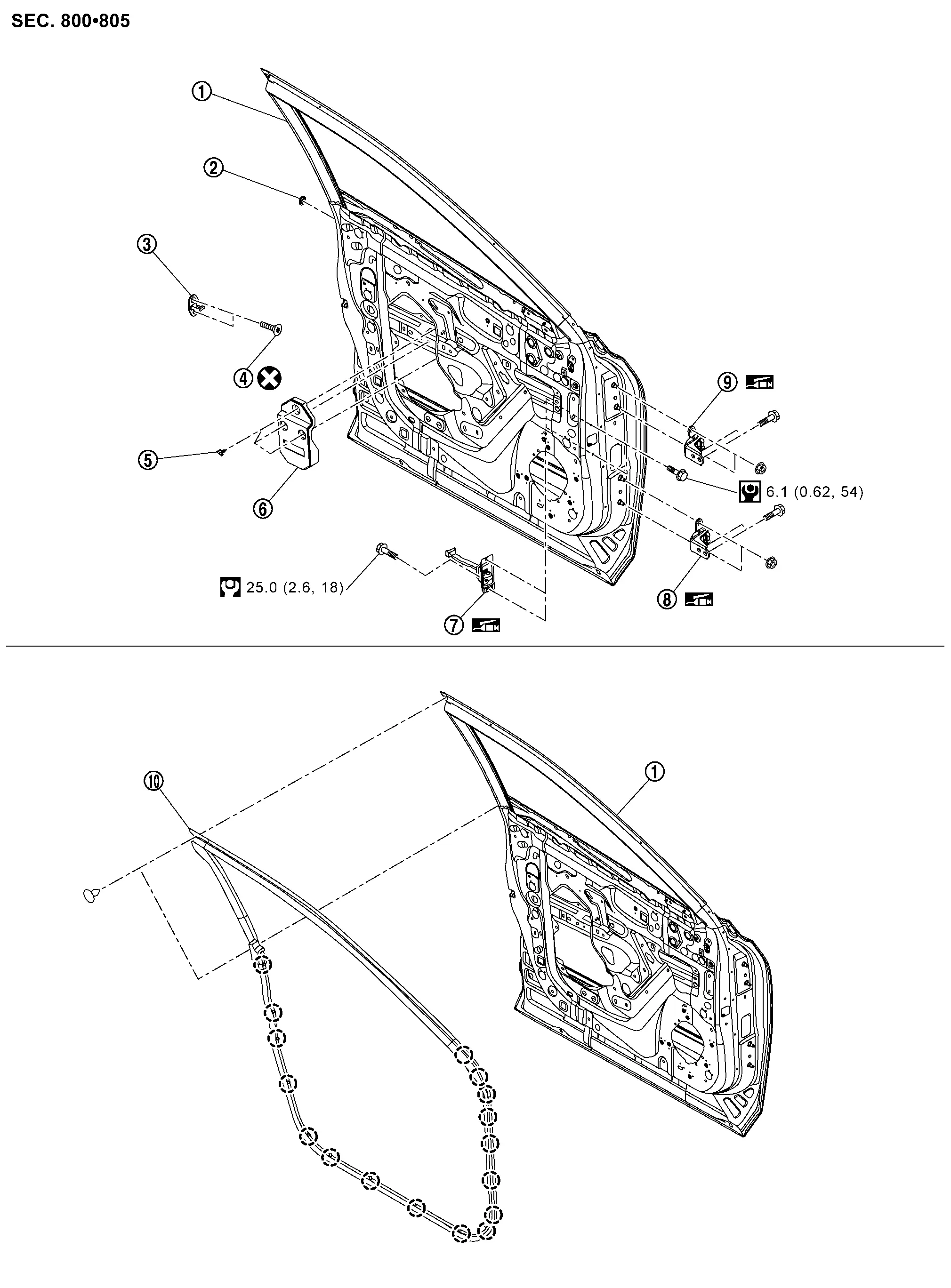
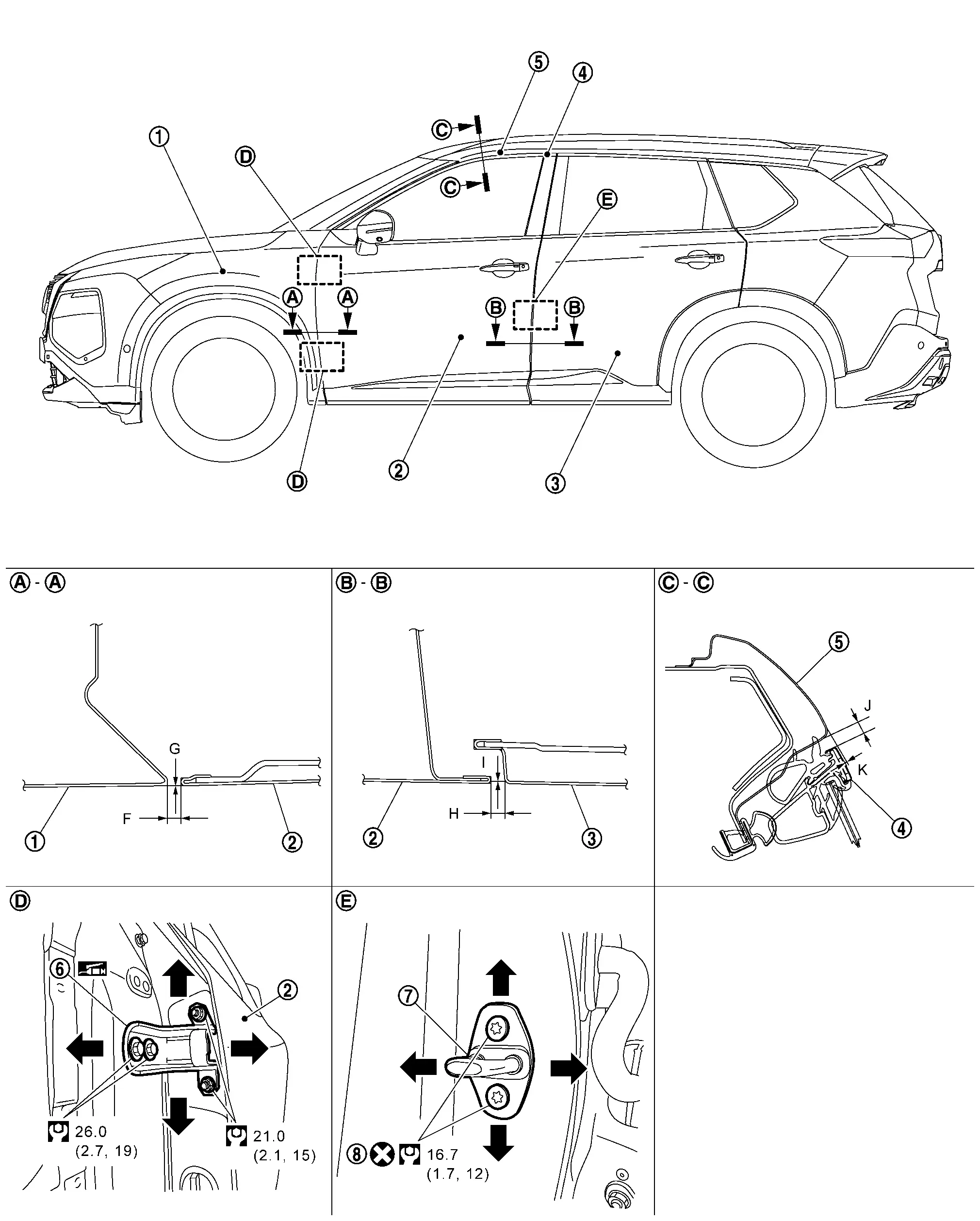
Exploded View
 |
Front door panel |  |
Grommet |  |
Front door striker |
 |
TORX bolt |  |
Clip |  |
Front outer pad |
 |
Front door check link |  |
Front door hinge (lower) |  |
Front door hinge (upper) |
 |
Front door weather-strip | ||||
 |
: Clip | ||||
 |
: Always replace after every disassembly. | ||||
 |
: Nôñm (kg-m, in-lb) | ||||
 |
: Nôñm (kg-m, ft-lb) | ||||
 |
: Body grease | ||||
Front Door Assembly
Removal and Installation
CAUTION:
-
Perform work with 2 workers, because it is heavy weight.
-
Support door with a proper material and use protective tape or shop cloth to protect door and body from falling and damage when removing and installing door assembly.
REMOVAL
Remove front door check link mounting bolt of vehicle body side.
Disengage pawl  of front door harness connector, and then release lock release lever
  according to numerical order 1ã2 indicated by arrows as shown in figure.
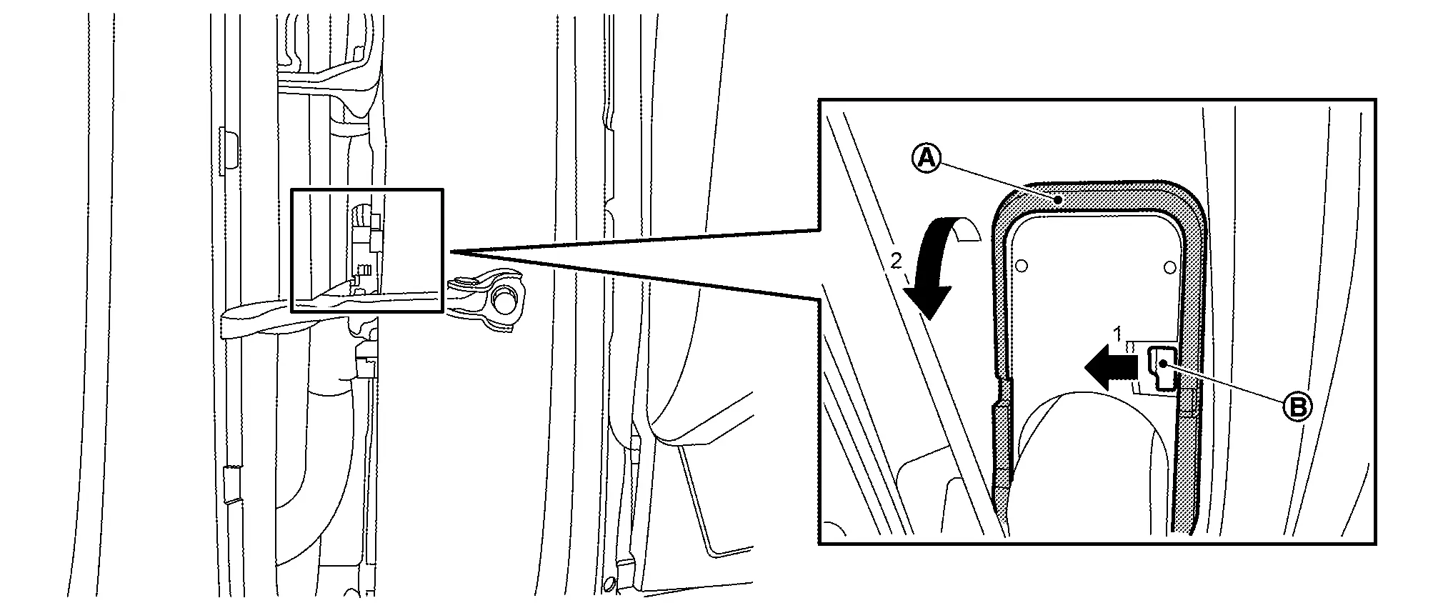
Disconnect front door harness connector.
Support front door assembly with a proper material to prevent it from falling.
WARNING:
Injury may occur if door assembly is not supported with a proper material when removing front door assembly.
Remove front door hinge mounting nuts, and then remove front door assembly.
INSTALLATION
Note the following items, and then install in the reverse order of removal.
CAUTION:
-
Before installation, apply anticorrosive agent onto mounting surface.
-
After installation, perform the fitting adjustment. Refer to Adjustment.
-
After installation, apply touch-up paint (the body color) onto the head of front door hinge mounting nuts.
-
After installation, check the open/close operation. Refer to Inspection.
-
If equipped with side camera, perform camera image calibration. Refer to Work Procedure (WITHOUT ProPILOT Assist 2.1) or Work Procedure (WITH ProPILOT Assist 2.1).
CAUTION:
Perform the calibration and perform the writing to the around view monitor control unit when removing and replacing each camera, removing the camera mounting parts (front grille, door mirror, etc.) and replacing the around view monitor control unit.
Inspection
Open and close the door. Check that door hinge and check link rotation portion moves smoothly.
Check door hinge rotating part for poor lubrication. Apply body grease if necessary.
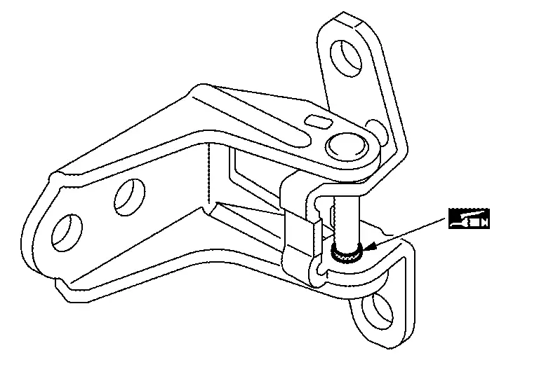
|
: Body grease |
Check door check link rotating part for poor lubrication. Apply body grease if necessary.
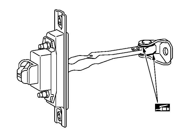
|
: Body grease |
Adjustment
FITTING ADJUSTMENT
Fitting Adjustment Standard Dimension
|
Front fender assembly | |
Front door panel | |
Rear door panel |
|
Front door sash molding | |
Body side outer | |
Front door hinge |
|
Front door striker | |
TORX bolt | ||
|
: Always replace after every disassembly. | ||||
|
: Nôñm (kg-m, ft-lb) | ||||
|
: Body grease | ||||
Unit: mm [in]
| Portion | Standard | |||
|---|---|---|---|---|
| Front door panel ã Front fender assembly | ã |
F | Clearance |
3.0 ã 5.0 [0.118 ã 0.197] |
| G | Surface height |
(ã1.0) ã (+1.0) [(ã0.039) ã (+0.039)] |
||
| Front door panel ã Rear door panel | ã |
H | Clearance |
3.4 ã 5.4 [0.134 ã 0.213] |
| I | Surface height |
(ã1.0) ã (+1.0) [(ã0.039) ã (+0.039)] |
||
| Front door sash molding ã Body side outer |  ã ã |
J | Clearance |
4.7 ã 7.7 [0.185 ã 0.303] |
| K | Surface height |
(ã0.5) ã (+2.5) [(ã0.020) ã (+0.098)] |
||
Check the clearance and surface height between front door and each part by visually and touching.
If the clearance and the surface height are out of specification, adjust them according to the procedures shown below.
Fitting Adjustment Procedure
Remove front fender assembly. Refer to Removal and Installation.
Loosen front door hinge mounting bolts.
Adjust the clearance of front door according to the fitting adjustment standard dimension by moving front door panel.
Tighten front door hinge mounting bolts to the specified torque.
CAUTION:
After tightening, apply touch-up paint (the body color) onto the head of hinge mounting bolts.
Install front fender assembly. Refer to Removal and Installation.
Loosen front door hinge mounting nuts.
Adjust the surface height of front door according to the fitting adjustment standard dimension by moving front door panel.
Tighten front door hinge mounting nuts to the specified torque.
CAUTION:
After tightening, apply touch-up paint (the body color) onto the head of hinge mounting nuts.
DOOR STRIKER ADJUSTMENT
Adjust front door striker so that it becomes parallel with door lock insertion direction.
Front Door Striker
Removal and Installation
REMOVAL
Remove TORX bolts, and then remove front door striker.
INSTALLATION
Note the following items, and then install in the reverse order of removal.
CAUTION:
-
Never reuse TORX bolt. Always replace it with a new one when it is removed.
-
After installation, perform the fitting adjustment. Refer to Adjustment.
Front Door Hinge
Removal and Installation
REMOVAL
Remove front door assembly. Refer to Removal and Installation.
Remove front fender assembly. Refer to Removal and Installation.
Remove front door hinge mounting bolts, and then remove front door hinge.
INSTALLATION
Note the following items, and then install in the reverse order of removal.
CAUTION:
-
Before installation, check the front door hinge rotating part for poor lubrication. Refer to Inspection.
-
Before installation, apply anticorrosive agent onto the mounting surface.
-
After installation, perform the fitting adjustment. Refer to Adjustment.
-
After installation, apply touch-up paint (the body color) onto the head of front door hinge mounting bolts and nuts.
-
After installation, check the open/close operation. Refer to Inspection.
Front Door Check Link
Removal and Installation
REMOVAL
Fully close front door glass.
Remove front door speaker. Refer to Removal and Installation.
Remove front door check link mounting bolt of Nissan Ariya vehicle body side.
Remove front door check link mounting bolts of front door panel, and then take front door check link out from the hole of front door panel.
INSTALLATION
Note the following item, and then install in the reverse order of removal.
CAUTION:
After installation, check the open/close operation. Refer to Inspection.
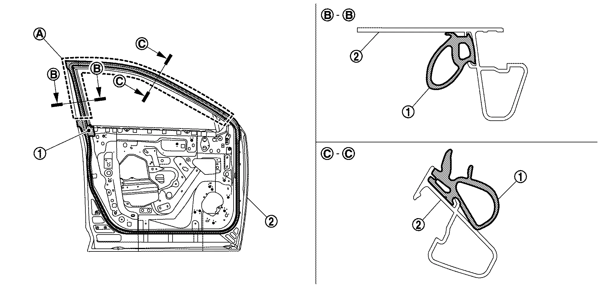
Front Door Weather-Strip
Removal and Installation
REMOVAL
Remove front door weather-strip rear side fixing clips .
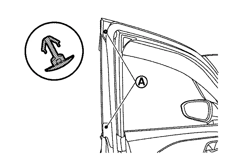
Apply protective tape (A) to front door panel around front door weather-strip fixing clips for preventing damage.
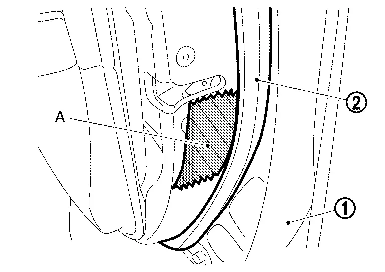
Disengage fixing clips on the reverse side of front door weather-strip using a remover tool (A).
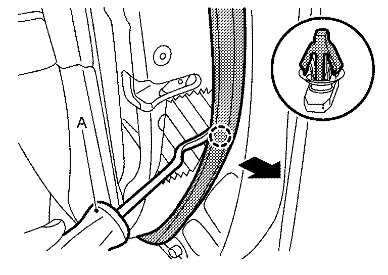
|
: Clip |
CAUTION:
-
Never damage front door panel.
-
When removing, never confuse the 2 types of front door weather-strip
fixing clips and .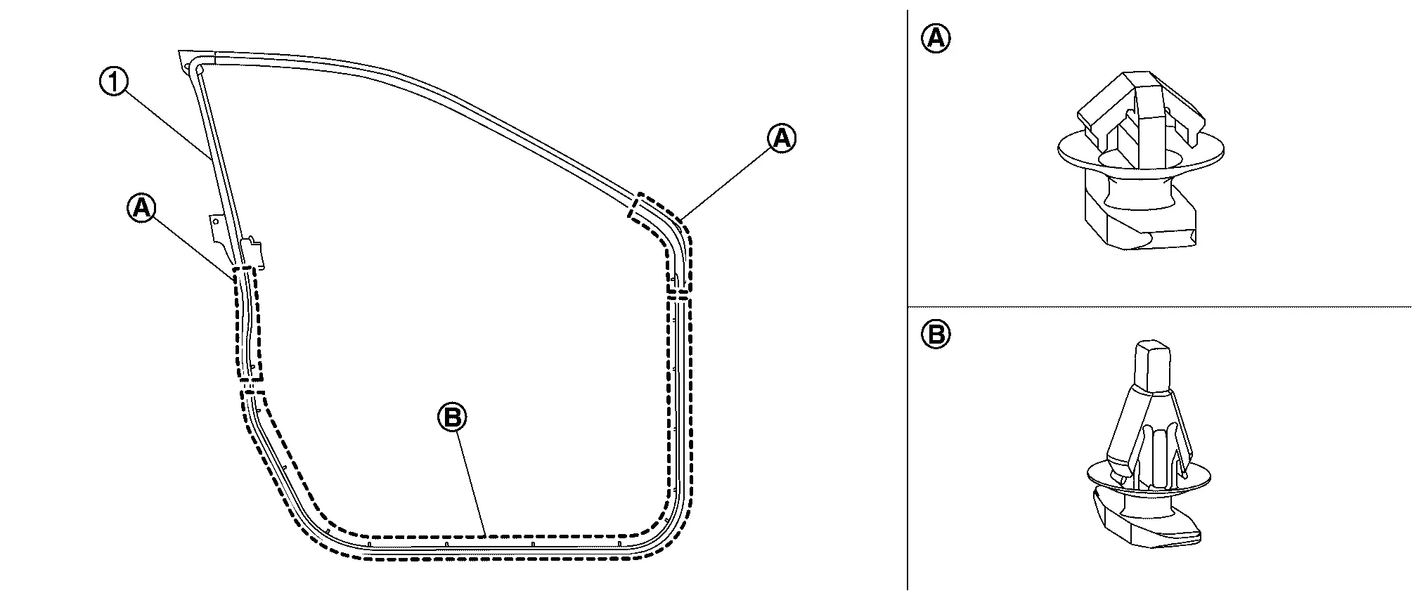
Remove front door check link mounting bolt of Nissan Ariya vehicle body side.
Remove front door weatherãstrip from front door panel.
INSTALLATION
Note the following item, and then install in the reverse order of removal.
CAUTION:
Install pant of front door weather-strip to ditch of front door panel surely.
Other materials:
Protection contre la corrosion
Facteurs de corrosion les plus courants
Accumulation de poussiû´re humide, de sable et de dûˋbris dans les panneaux de carrosserie, les orifices et les zones peu ventilûˋes.
Dommages de la peinture ou des revûˆtements protecteurs causûˋs par des projections de gravillons ou de petits accidents ...
Prûˋcautions pour ûˋviter tout risque de collision et de tonneau
AVERTISSEMENT
Une utilisation imprudente ou dangereuse de ce vûˋhicule peut entraûÛner une perte de contrûÇle, un accident grave ou un retournement.
Restez vigilant et adoptez une conduite prudente en toutes circonstances. Respectez scrupuleusement le code de la route et adaptez votre vitesse au ...
C10b0-09 Parking Brake Actuator (rh)
DTC Description
DTC DETECTION LOGIC DTC No.
CONSULT screen terms
(Trouble diagnosis content) DTC detection condition
C10B0
09
Parking brake actuator (RH)
[Parking brake actuator (right)]
Diagnosis condition
When parking brake is apply
Signal (terminal)
ã
Threshol ...