Nissan Rogue (T33) 2021-Present Service Manual: Removal and Installation :: Door Mirror
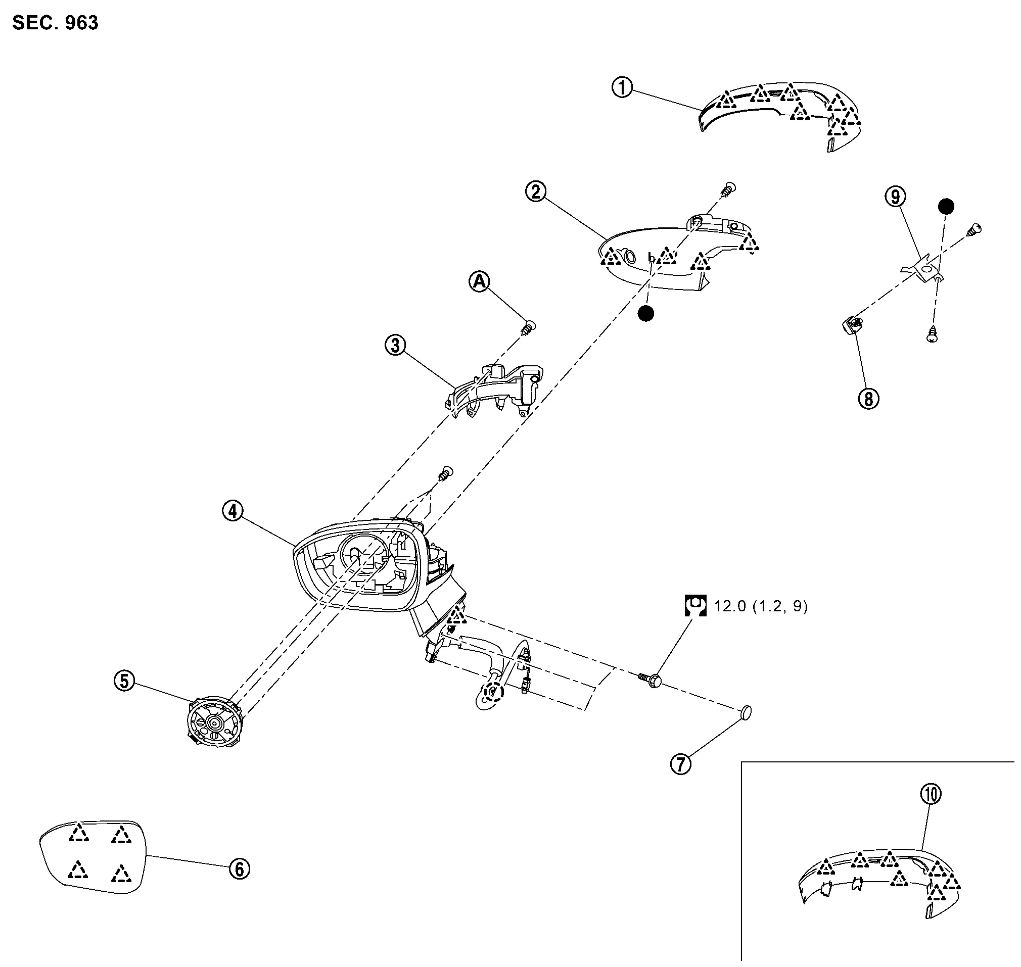
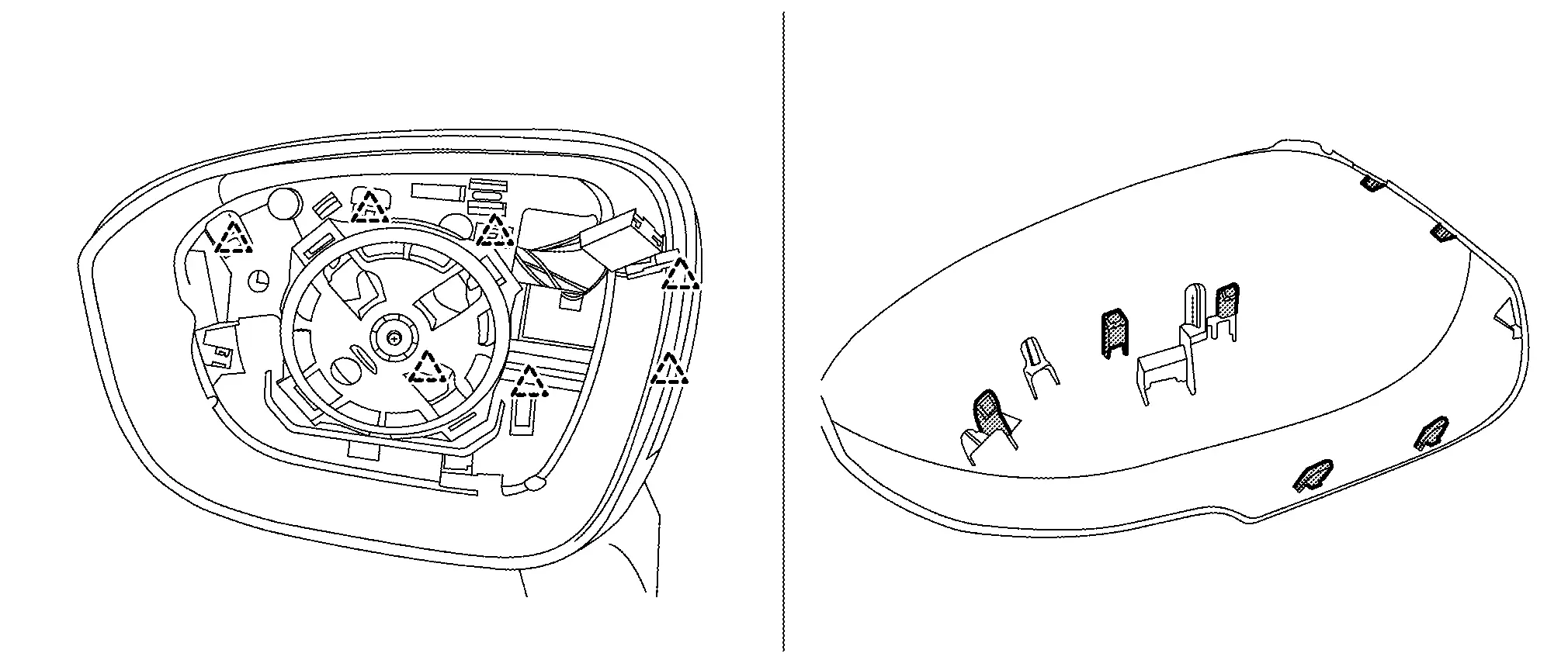
Exploded View
 |
Door mirror cover (with side turn signal lamp) |  |
Door mirror finisher |  |
Side turn signal lamp (with side turn signal lamp) |
 |
Door mirror base |  |
Door mirror actuator |  |
Glass mirror |
 |
Blind cap |  |
Side camera (with side camera) |  |
Side camera bracket (with side camera) |
 |
Door mirror cover (without side turn signal lamp) | ||||
 |
Screw (with side turn signal lamp) | ||||
 |
: Clip | ||||
 |
: Pawl | ||||
 |
ïžNmïžkg-m, in-lbïž | ||||
 : Indicated that the part is connected at points with same symbol in actual Nissan Ariya vehicle. : Indicated that the part is connected at points with same symbol in actual Nissan Ariya vehicle. |
|||||
Door Mirror Assembly
Removal and Installation
REMOVAL
CAUTION:
Never damage the front door panel.
Remove front door finisher. Refer to Removal and Installation.
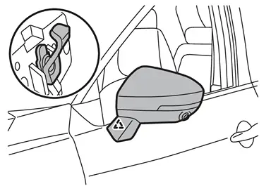
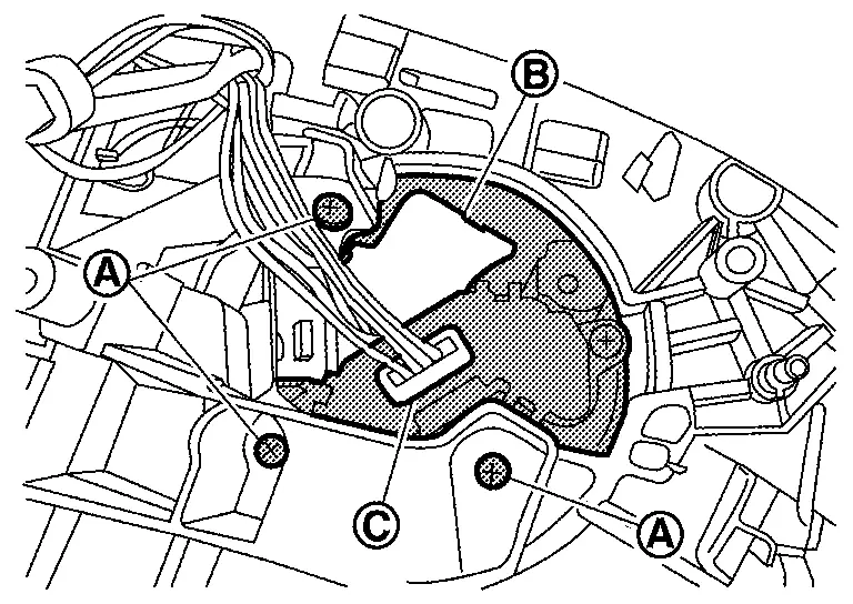
Disconnect door mirror assembly harness connector .
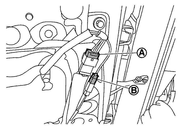
Disconnect side camera harness connector (B) (if so equipped with side camera).
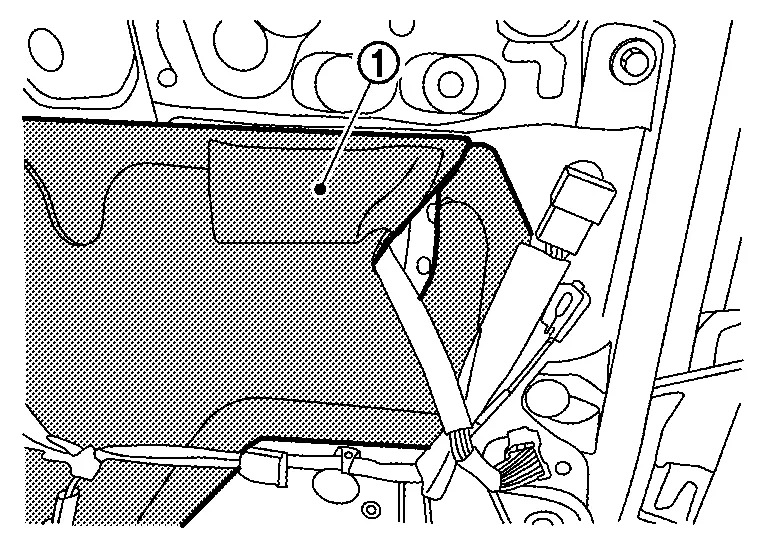
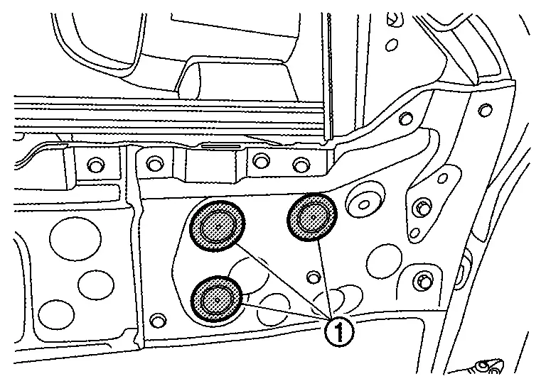
Remove front door sealing screen (1). Refer to Removal and Installation.
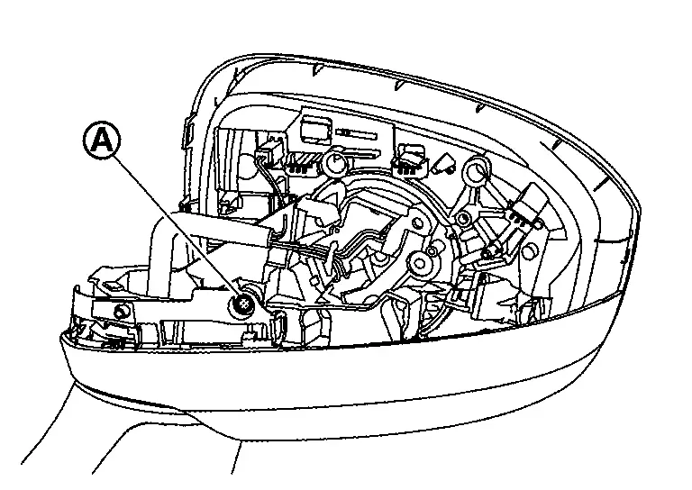
Remove harness clip (A).
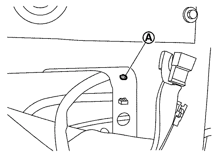
Remove blind cap (1).
Remove door mirror assembly mounting bolts .
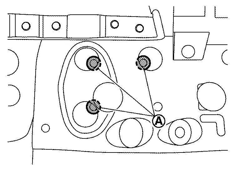
Disengage door mirror assembly fixing pawl, and then remove door mirror assembly.
|
: Pawl |
INSTALLATION
Installation in the reverse order of removal.
If equipped with side camera, perform camera image calibration. Refer to Work Procedure (WITHOUT ProPILOT Assist 2.1) or Work Procedure (WITH ProPILOT Assist 2.1).
CAUTION:
Perform the calibration and perform the writing to the around view monitor control unit when removing and replacing each camera, removing the camera mounting parts (front grille, door mirror, etc.) and replacing the around view monitor control unit.
Disassembly and Assembly
DISASSEMBLY
Remove door mirror assembly. Refer to Removal and Installation.
Remove glass mirror. Refer to Removal and Installation.
Remove door mirror cover. Refer to Removal and Installation.
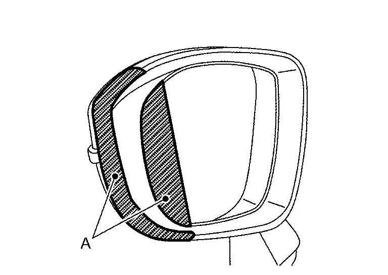
Remove door mirror finisher fixing screws (A).
-
With side turn signal lamp
-
Without side turn signal lamp
Disengage door mirror finisher fixing pawls, and then remove door mirror finisher.
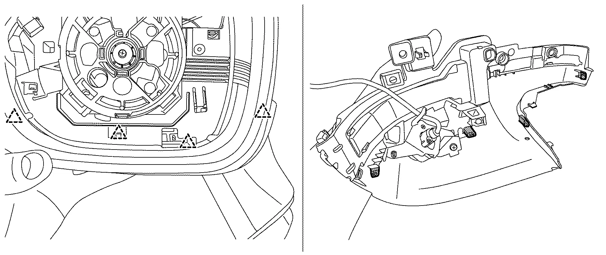
|
: Pawl |
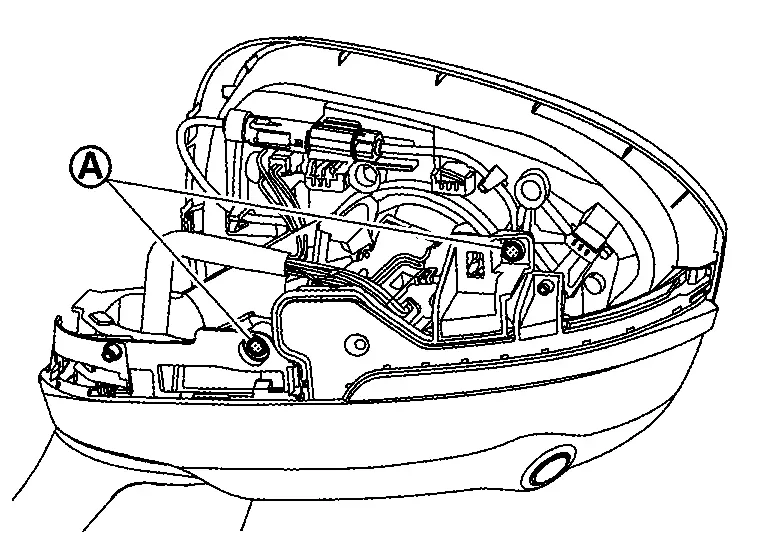
Disconnect side camera harness connector (A) (with side camera).
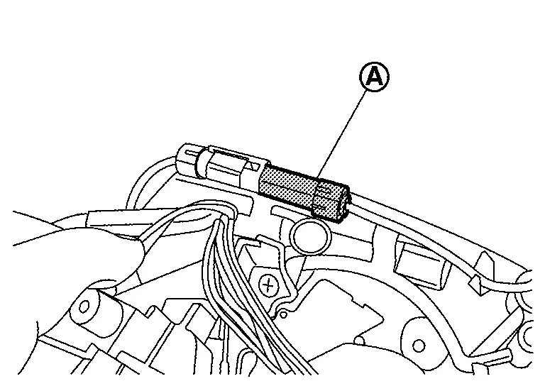
Remove side camera fixing screw (A), and then remove side camera (with side camera).
Remove side turn signal lamp (with side turn signal lamp). Refer to Removal and Installation.
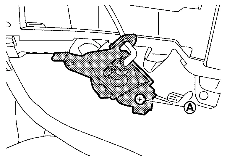
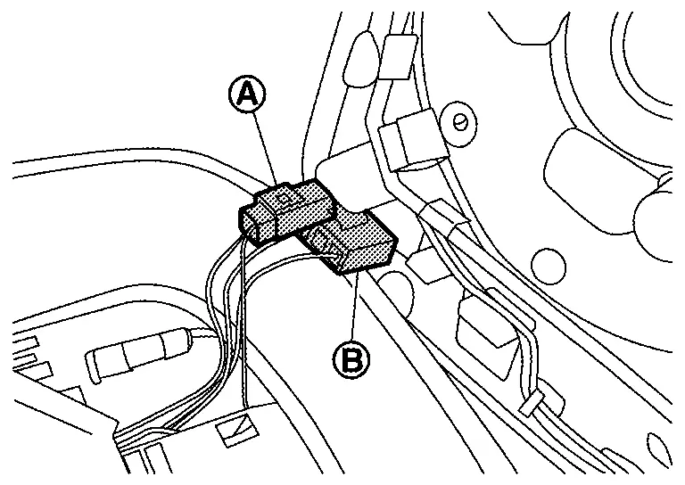
Remove door mirror actuator fixing screws (A).
Disconnect harness connectors (B) and (C), and then remove door mirror actuator.
ASSEMBLY
Assembly is in the reverse order of disassembly.
Glass Mirror
Removal and Installation
REMOVAL
Place glass mirror inward.
Apply protective tapes (A) on the part to protect it from damage.
Insert remover tool (A) into the recess at outside between glass mirror and door mirror actuator, and then disengage glass mirror fixing pawls.
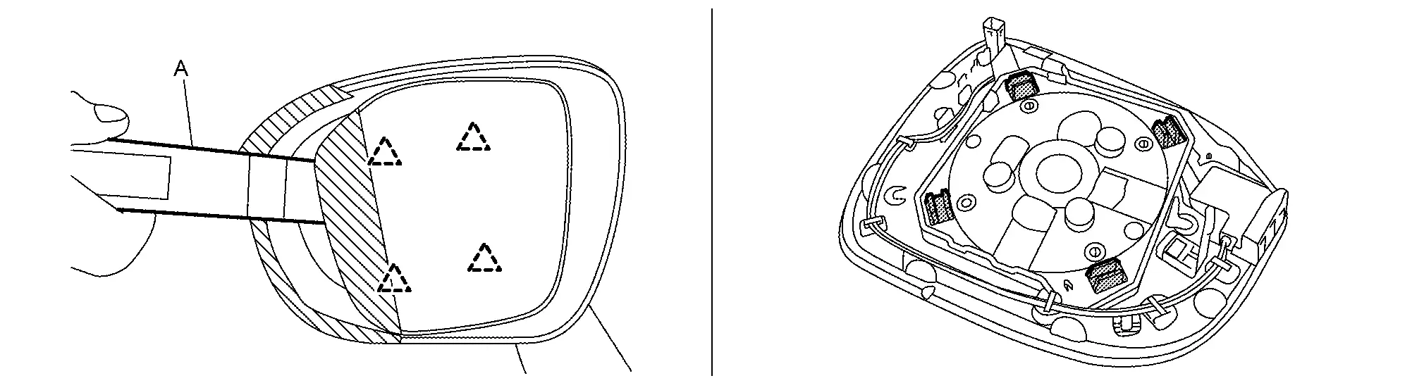
CAUTION:
Remove the fixing pawls slowly so they are not damaged.
|
: Pawl |
Disconnect harness connector and  .
.
Remove glass mirror.
INSTALLATION
Note the following item, and then install in the reverse order of removal.
CAUTION:
After installation, visually check that fixing pawls are securely engaged.
Door Mirror Cover
Removal and Installation
REMOVAL
Remove glass mirror. Refer to Removal and Installation.
Disengage door mirror cover fixing pawls.
|
: Pawl |
Remove door mirror cover.
INSTALLATION
Note the following item, and then install in the reverse order of removal.
CAUTION:
After installation, visually check that fixing pawls are securely engaged.
Other materials:
Accessory Relay
Diagnosis Procedure
CHECK ACCESSORY RELAY POWER SUPPLY
Disconnect accessory relay connector.
Check voltage between accessory relay harness connector and ground.
(+) (â)
Voltage
(Approx.)
Accessory relay
Connector Terminal
J-5
2
Ground
Battery voltage
3
...
B2740-82 Ipdm E/r
DTC Description
DTC DETECTION LOGIC DTC CONSULT screen items (Trouble diagnosis content) DTC detection condition
B2740-82
IPDM E/R
Diagnosis condition
When ignition switch is ON
Signal (terminal)
â
Threshold
Communication error between sonar control unit and IPDM E/R ...
Direction assistÃĐe intelligente (ModÃĻles ProPILOT Assist)
La commande de direction assistÃĐe liÃĐe au systÃĻme ProPILOT Assist du Nissan Rogue permet de stabiliser le vÃĐhicule au centre de sa voie. Vous pouvez activer ou suspendre cette aide via l'interrupteur physique ou directement dans le menu "Assistance au conducteur" de l'ÃĐcran multifonction ...