Nissan Rogue (T33) 2021-Present Service Manual: Removal and Installation :: Body Side Trim
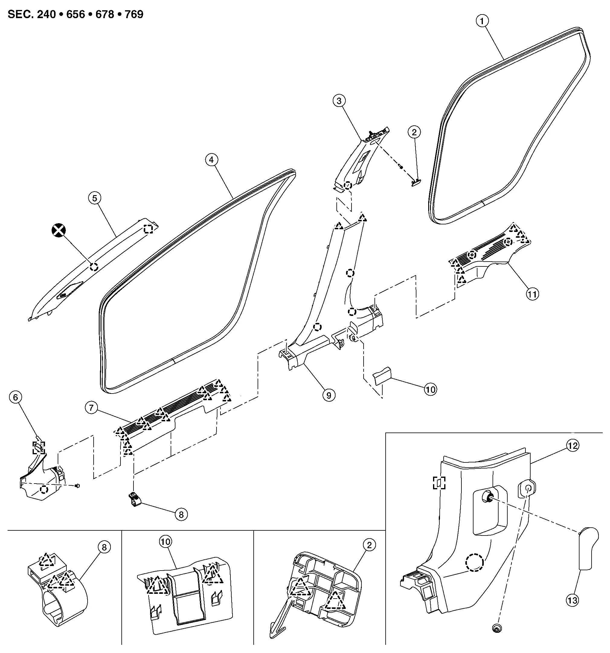
Exploded View
With ProPILOT Assist 2.1

| 1. | Rear body side welt | 2. | Bolt cap | 3. | Center pillar upper garnish |
| 4. | Front body side welt | 5. | Front pillar garnish | 6. | Dash side finisher RH |
| 7. | Front kicking plate | 8. | Harness protector | 9. | Center pillar lower garnish |
| 10. | Seat belt cover | 11. | Rear kicking plate | 12. | Dash side finisher LH |
| 13. | Hood lock control handle | ||||
 |
: Clip | ||||
 |
: Pawl | ||||
 |
: Metal clip | ||||
 |
: Always replace after every disassembly. | ||||
Without ProPILOT Assist 2.1
| 1. | Rear body side welt | 2. | Bolt cap | 3. | Center pillar upper garnish |
| 4. | Front body side welt | 5. | Front pillar garnish | 6. | Dash side finisher RH |
| 7. | Front kicking plate | 8. | Harness protector | 9. | Center pillar lower garnish |
| 10. | Seat belt cover | 11. | Rear kicking plate | 12. | Dash side finisher LH |
| 13. | Hood lock control handle | ||||
|
: Clip | ||||
|
: Pawl | ||||
|
: Metal clip | ||||
|
: Always replace after every disassembly. | ||||
Front Pillar Garnish
Removal and Installation
CAUTION:
Never damage the body panel.
REMOVAL
Release front pillar garnish portion of front body side welt.
Disengage front pillar garnish fixing metal clip and anchor clip according to numerical order 1→2 indicated by arrows as shown in the figure.
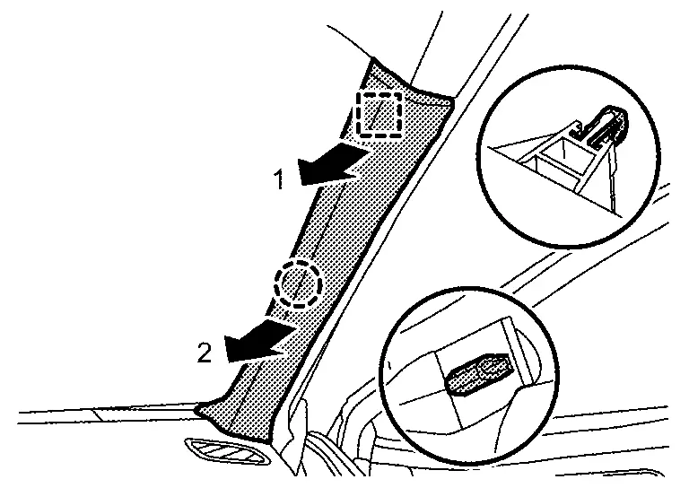
|
: Anchor clip |
|
: Metal clip |
Cut anchor clip portion.
Disengage front pillar garnish fixing portions, and then remove front pillar garnish.
Remove tether strap fixing screw [A (if equipped)].
Disengage tweeter harness connector (if equipped).
Remove front pillar garnish anchor clip from body panel.
INSTALLATION
Note the following items, and then install in the reverse order of removal.
CAUTION:
-
Always replace anchor clip with a new one after every removal.
-
Be sure to install anchor clip to front pillar garnish before installing front pillar garnish.
-
Visually check metal clip for deformation and damage during installation. Replace with a new one if necessary.
-
Check in advance that anchor clip and metal clip are accurately aligned with the portions on body panel, and then install by pressing in.
Dash Side Finisher
Removal and Installation
CAUTION:
Never damage the body panel.
REMOVAL
Remove front kicking plate. Refer to Removal and Installation.
Release dash side finisher portion of front body side welt.
Remove hood lock control handle (LH only). Refer to Removal and Installation.
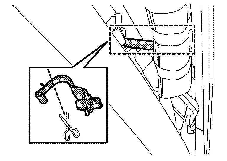
Disengage dash side finisher from dash side clip  .
.
Disengage dash side finisher fixing clip.
|
: Clip |
Using a suitable tool, release metal clip and remove dash side finisher.
: Metal clip
INSTALLATION
Note the following items, and then install in the reverse order of removal.
CAUTION:
-
Visually check clip for deformation and damage during installation. Replace with new ones if necessary.
-
Check in advance that clip is accurately aligned with the portions on body panel, and then install by pressing in.
Kicking Plate
Removal and Installation
CAUTION:
Never damage the body panel.
REMOVAL
Front Kicking Plate
Disengage front kicking plate fixing pawls according to numerical order 1→4 indicated by arrows as shown in the figure.
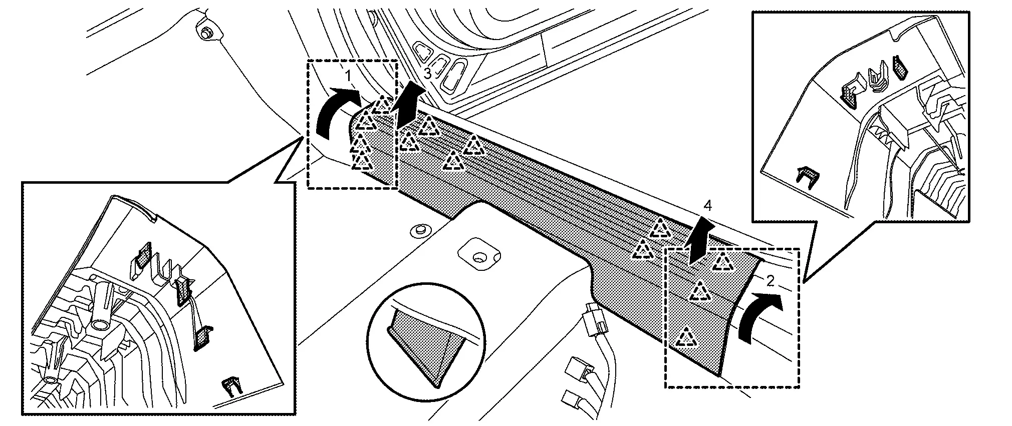
 NOTE:
NOTE:
Without ProPILOT Assist 2.1 shown, with ProPILOT Assist 2.1 similar.
|
: Pawl |
Rear Kicking Plate
Disengage rear kicking plate fixing pawls and clips according to numerical order 1→3 indicated by arrows as shown in the figure.
|
: Clip |
|
: Pawl |
INSTALLATION
Note the following item, and then install in the reverse order of removal.
CAUTION:
-
Visually check clip for deformation and damage during installation. Replace with new ones if necessary.
-
Check in advance that clips and pawls are accurately aligned with the portions on dash side finisher, center pillar lower garnish, luggage side lower finisher and body panel, and then install by pressing in.
Body Side Welt
Removal and Installation
CAUTION:
-
Never excessively pull body side welt.
-
Never damage the body panel.
REMOVAL
Front Body Side Welt
-
Remove front kicking plate. Refer to Removal and Installation.
-
Remove front body side welt.
Rear Body Side Welt
-
Remove rear kicking plate. Refer to Removal and Installation.
-
Remove rear body side welt.
INSTALLATION
Install in the reverse order of removal.
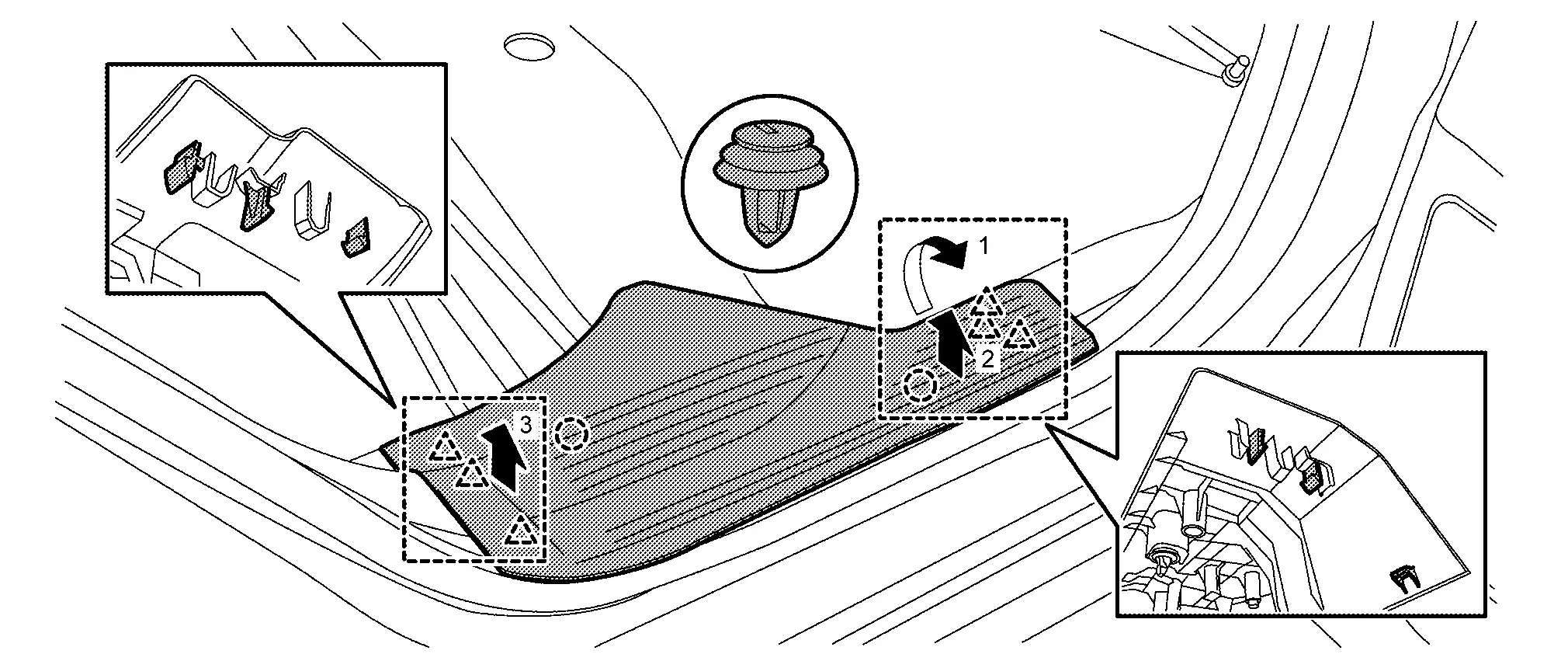
Center Pillar Lower Garnish
Removal and Installation
CAUTION:
Never damage the body panel.
REMOVAL
Fully open front door and rear door.
Remove front body side welt and rear body side welt. Refer to Removal and Installation.
Disengage seat belt cover fixing pawls, and then remove seat belt cover.
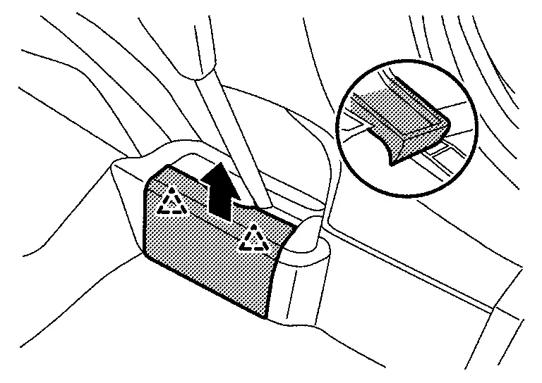
|
: Pawl |
Disengage center pillar lower garnish upper side fixing pawls.
|
: Pawl |
Disengage center pillar lower garnish fixing clips, and then remove center pillar lower garnish.
NOTE:
Without ProPILOT Assist 2.1 shown, with ProPILOT Assist 2.1 similar.
|
: Clip |
INSTALLATION
Note the following items, and then install in the reverse order of removal.
CAUTION:
-
Visually check clips for deformation and damage during installation. Replace with new ones if necessary.
-
Check in advance that clips and pawls are accurately aligned with the portions on center pillar upper garnish and body panel, and then install by pressing in.
Center Pillar Upper Garnish
Removal and Installation
CAUTION:
Never damage the body panel.
REMOVAL
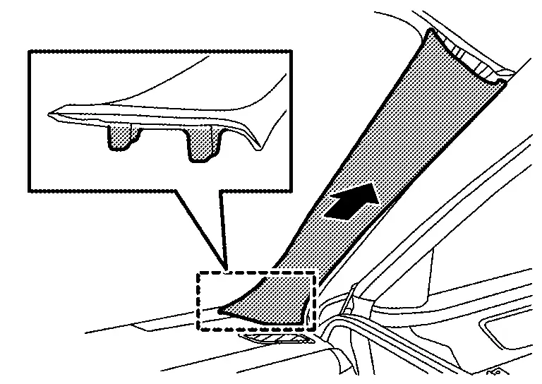
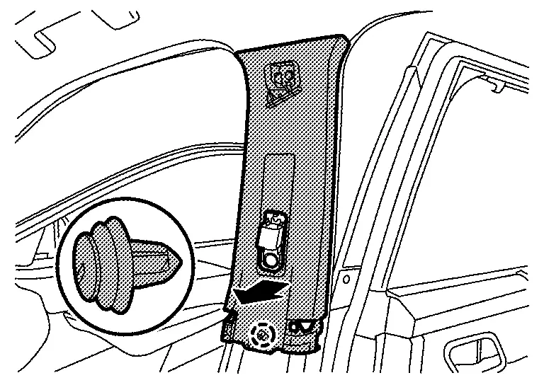
Remove center pillar lower garnish. Refer to Removal and Installation.
Remove front seat belt anchor. Refer to Removal and Installation .
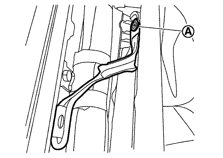
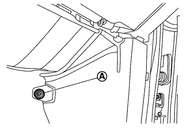
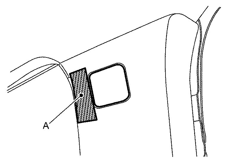
Apply protective tape (A) on f center pillar upper garnish to protect it from damage.
Disengage bolt cap fixing pawls using a remover tool (A), and then remove bolt cap.
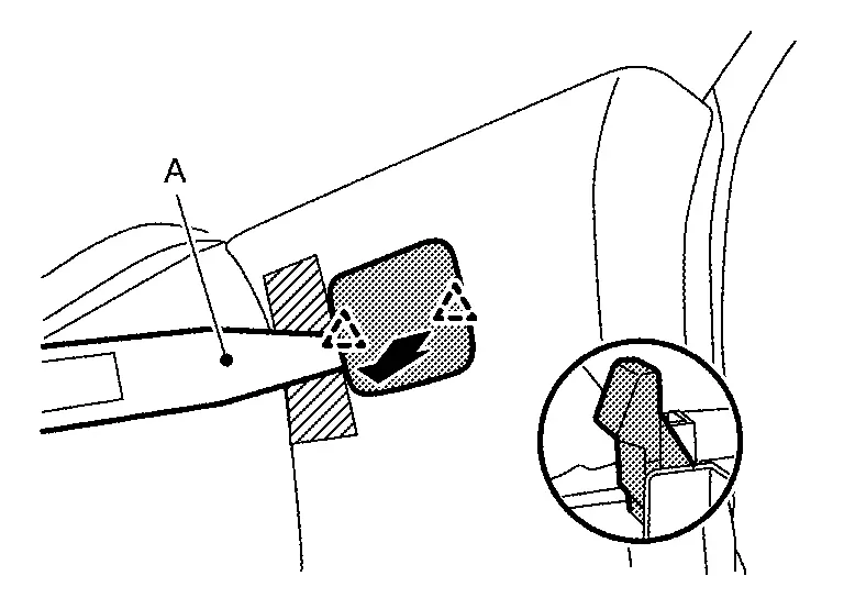
|
: Pawl |
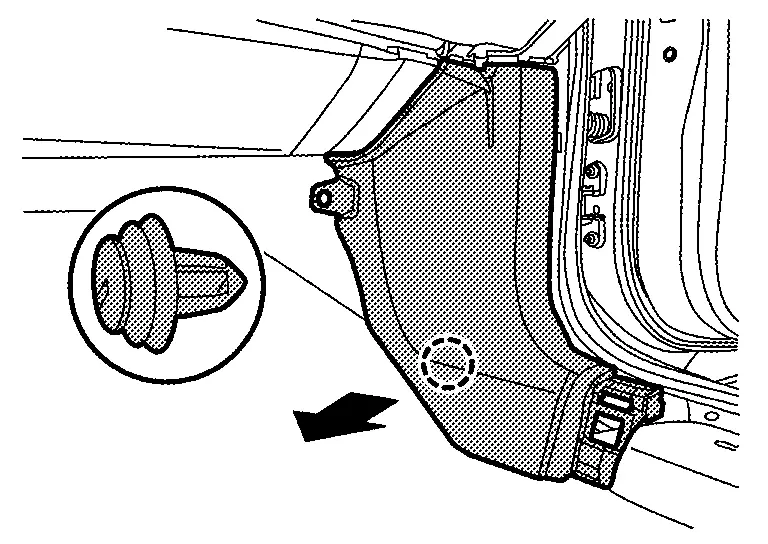
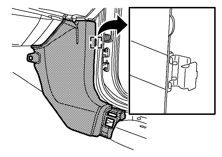
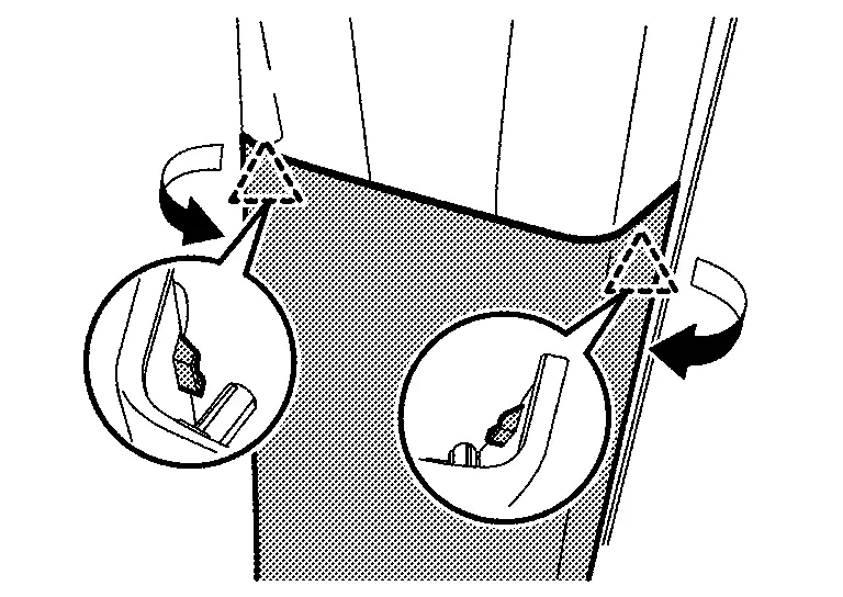
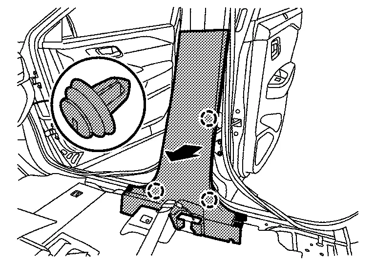
Remove center pillar upper garnish mounting bolt.
Remove center pillar upper garnish lower side fixing clip, and then remove center pillar upper garnish.
|
: Clip |
INSTALLATION
Note the following item, and then install in the reverse order of removal.
CAUTION:
-
Visually check clip for deformation and damage during installation. Replace with new ones if necessary.
-
Check in advance that clip is accurately aligned with the hole on body panel, and then install by pressing in.
Other materials:
Informations de base et fonctionnement
Exemple d'affichage dynamique
L’affichage tête haute (Head-Up Display ou HUD) du Nissan Rogue est une technologie de pointe conçue pour projeter les données de conduite essentielles directement dans votre champ de vision. Cette innovation permet au conducteur du Nissan Rogue de rester co ...
P11b0 Vcr Target Angle (cold Start)
DTC Description
DTC DETECTION LOGIC DTC
CONSULT screen terms
(Trouble diagnosis content)
DTC detection condition
P11B0
00
VCR target angle (cold start)
[Variable compression ratio target angle (cold start)]
Diagnosis condition
Engine cold start
Signal (terminal)
â ...
P1c90-49 Sub Starter & Generator
DTC Description
DTC DETECTION LOGIC DTC No. CONSULT screen terms (Trouble diagnosis content) DTC detection condition
P1C90-49
Sub starter & generator
(Sub starter & generator)
Diagnosis condition
Engine running at idle
Signal (terminal)
-
Threshold
Sub starte ...