Nissan Rogue (T33) 2021-Present Service Manual: Rear Propeller Shaft: Cvj-Cvj-C :: Removal and Installation. Rear Propeller Shaft
Rear Propeller Shaft
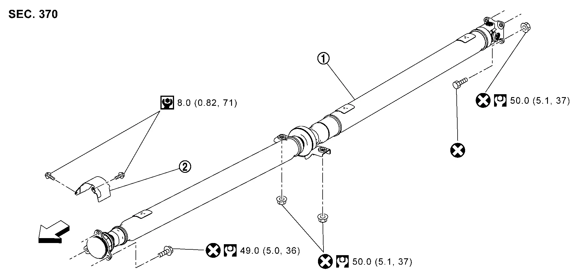
Exploded View
 |
Propeller shaft assembly |  |
Heat shield plate | ||
 : N·m (kg-m, in-lb) : N·m (kg-m, in-lb) |
|||||
 : N·m (kg-m, ft-lb) : N·m (kg-m, ft-lb) |
|||||
 : Always replace after every disassembly. : Always replace after every disassembly. |
|||||
Removal and Installation
REMOVAL
Remove engine under cover. Refer to Exploded View.
Disconnect fixed parts between main muffler and exhaust front tube. Refer to Removal and Installation.
Remove heat insulator (1) after removing clips of floor insulator.
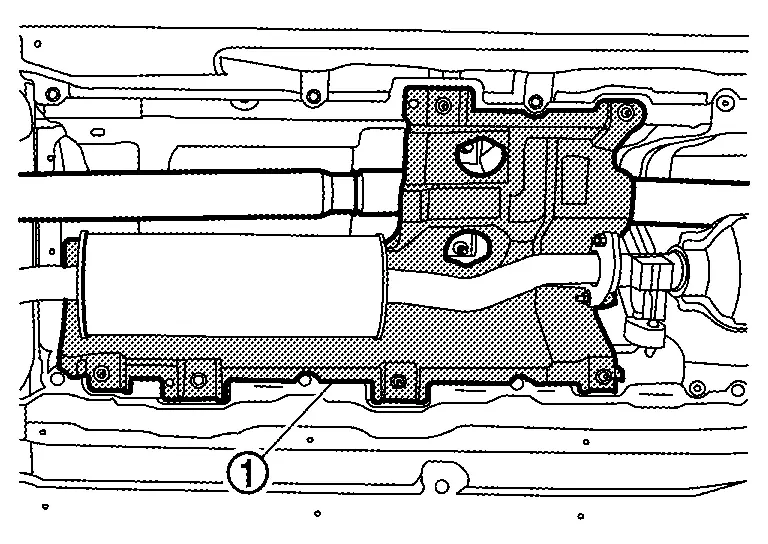
CAUTION:
Never bend heat insulator.
Put matching marks (A) on propeller shaft flange yoke and transfer companion flange.
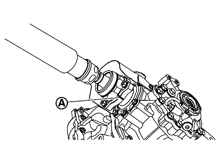
CAUTION:
For matching mark, use paint. Never damage propeller shaft flange yoke and transfer companion flange.
Put matching marks (A) on propeller shaft flange yoke and rear final drive companion flange.
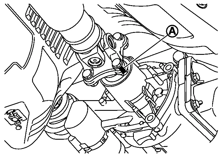
CAUTION:
For matching mark, use paint. Never damage propeller shaft flange yoke and rear final drive companion flange.
Loosen mounting nuts of center bearing mounting bracket.
 NOTE:
NOTE:
Tighten mounting nuts temporarily to prevent drop of propeller shaft.
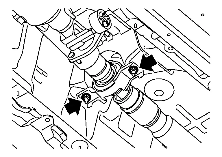
Remove propeller shaft assembly fixing bolts, and separate propeller shaft assembly from transfer companion flange.
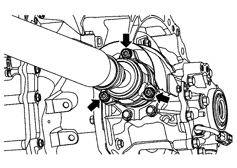
Remove propeller shaft assembly fixing bolts and nuts, and separate propeller shaft assembly from rear final drive companion flange.
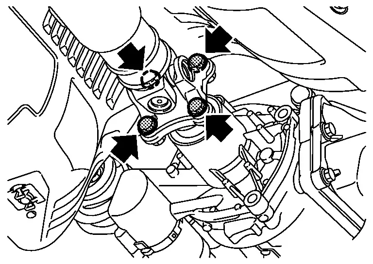
Remove center bearing mounting bracket mounting nuts.
Remove propeller shaft assembly.
CAUTION:
-
Constant velocity joint must be handled with care.
-
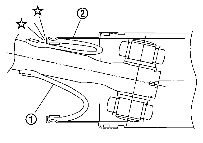
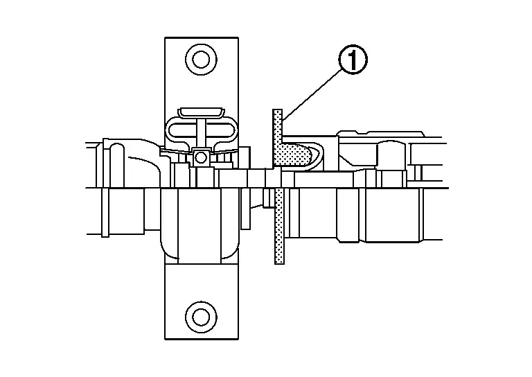
If constant velocity joint was bent during propeller shaft assembly removal, installation, or transportation, its boot (1) may be damaged. Wrap boot interference area to metal part (2) with shop cloth or rubber to protect boot from breakage.
-
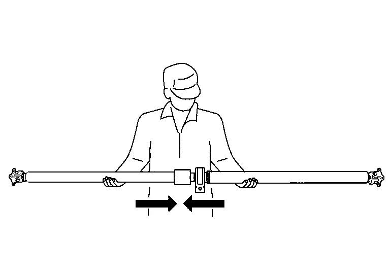
Since no retaining pin is included in sliding direction, the boot may be damaged or dropped if the constant velocity joint is slid out 25 mm (0.98 in) or more from the original length. Therefore, handle constant velocity joint by sliding it inward.
Remove heat shield plate from transfer if necessary.
Perform inspection after removal. Refer to Inspection.
INSTALLATION
Note the following, and install in the reverse order of removal.
-
For non-reusable parts, refer to Exploded View.
-
For each tightening torque, refer to Exploded View.
-
Clean and degrease the thread and seat of heat shield plate mounting bolts.
-
-
Remove any moisture, oil, or foreign material from matching surface on transfer companion flange, rear final drive companion flange and propeller shaft flange.
-
Align matching marks (A) to install propeller shaft flange yoke and rear final drive companion flange.
-
Align matching marks (A) to install propeller shaft flange yoke and transfer companion flange.
-
If propeller shaft assembly or final drive assembly has been replaced, connect them as follows:
-
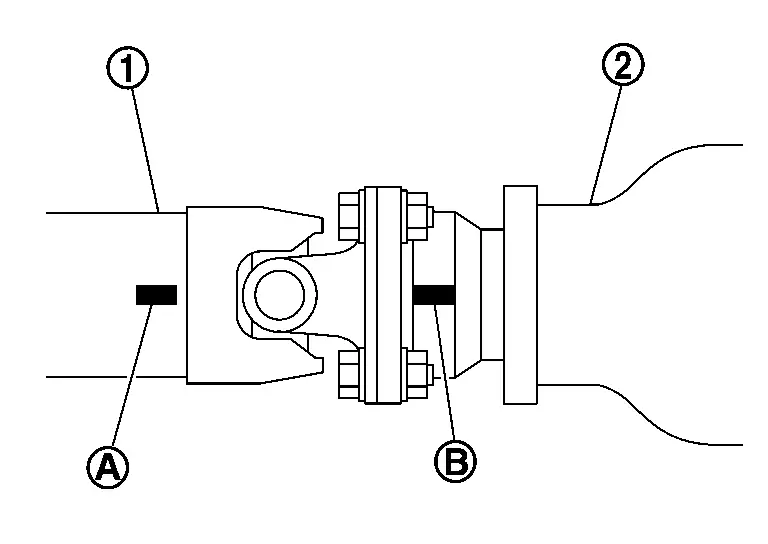
Install propeller shaft (1) while aligning its matching mark (A) of propeller shaft with matching mark (B) of final drive (2) on the joint as close as possible.
-
-
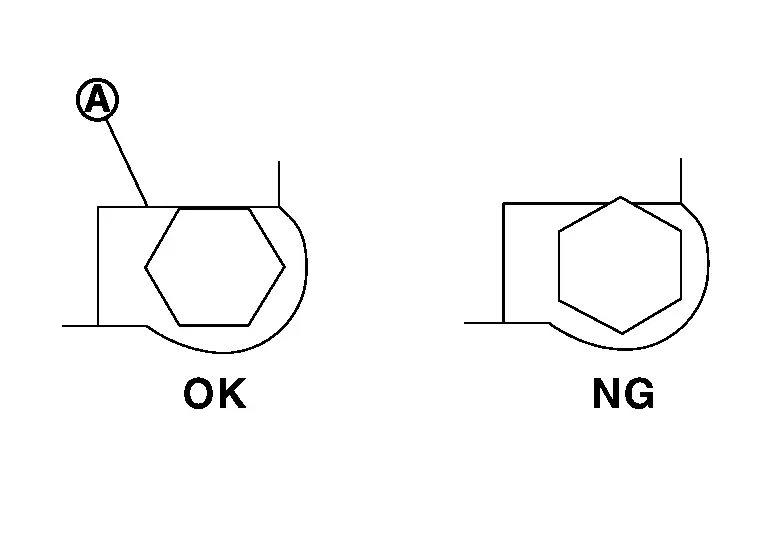
The bolt head should not become out of alignment due to interference between the bolt hexagonal head and the stopper (A).
-
Protector (1) on boot interference area must be removed after installing propeller shaft assembly.
-
Perform inspection after installation. Refer to Inspection.
Inspection
INSPECTION AFTER REMOVAL
Appearance
Check propeller shaft tube surface for dents or cracks. If malfunction is detected, replace propeller shaft assembly.
Propeller Shaft Runout
Check propeller shaft runout at measuring points with a dial indicator. If runout exceeds specifications, replace propeller shaft assembly.
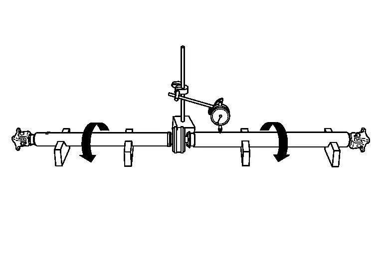
| Propeller shaft runout | : Refer to Propeller Shaft Tube. |
-
Propeller shaft runout measuring point (Point “
 ”).
”).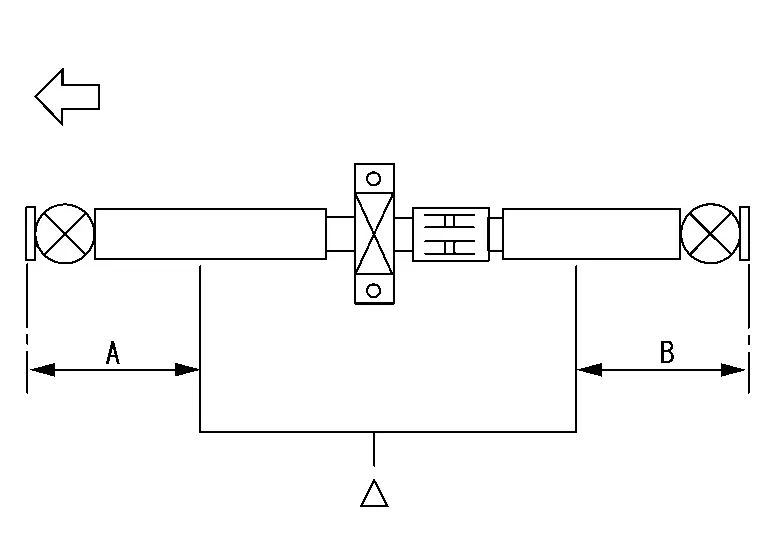

: Front side Dimension A : 554 mm (21.81 in) B : 546 mm (21.5 in)
Journal Axial Play
As shown in the figure, while fixing yoke on one side, check axial play of joint. If it is outside the standard, replace propeller shaft assembly.
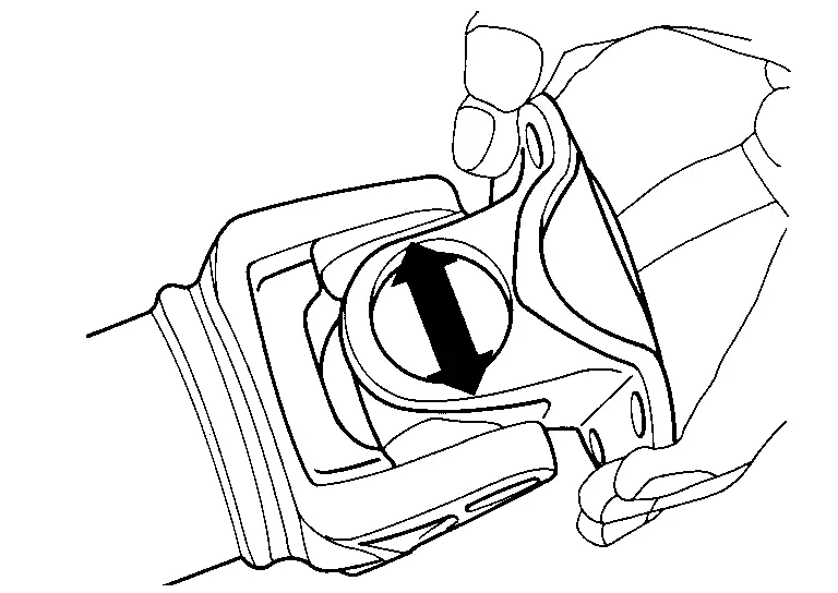
| Journal axial play | : Refer to Journal. |
CAUTION:
Never disassemble joints.
Center Bearing
Check center bearing for noise and damage. If malfunction is detected, replace propeller shaft assembly.
CAUTION:
Never disassemble center bearing.
INSPECTION AFTER INSTALLATION
After assembly, perform a driving test to check propeller shaft vibration. If vibration occurred, separate propeller shaft from final drive. Reinstall propeller shaft by changing the phase between companion flange and propeller shaft by the one bolt hole at a time. Then perform driving test and check propeller shaft vibration again at each point.
Other materials:
Steering Switch Signal a Circuit
Component Function Check
CHECK COMBINATION METER INPUT SIGNAL
CONSULT
Ignition switch ON.
Select “Steering switch input” in “Data monitor” mode of “M&A”.
Check that the function operates normally according to the following conditions:
Condition Value
CONTRO ...
U2a8c-88 Ethernet Circuit
DTC Description
DTC DETECTION LOGIC DTC No. CONSULT screen terms DTC detected condition
U2A8C-88
Ethernet circuit
Diagnosis condition
When ignition switch is ON.
Signal (terminal)
—
Threshold
Lost ethernet communication with AV control unit
Diagnosis delay time ...
Removal and Installation. Hood Lock
Exploded View
Hood lock
Hood lock release cable assembly
Hood lock release handle
: Clip
: N·m (kg-m, in-lb)
: Body grease
Hood Lock
Removal and Installation
REMOVALRemove front grill cover. Refer to Removal and Installation.
Disconnect hood lock switch har ...