Nissan Rogue (T33) 2021-Present Service Manual: Rear Final Drive: R145 :: Removal and Installation
Side Oil Seal
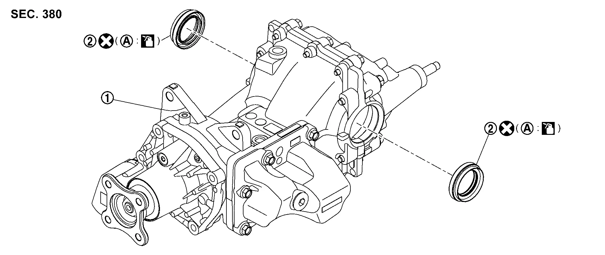
Exploded View
 |
Rear final drive assembly |  |
Side oil seal | ||
 |
Outer circumference | ||||
 : Always replace after every disassembly. : Always replace after every disassembly. |
|||||
 : Apply gear oil. : Apply gear oil. |
|||||
Removal and Installation
REMOVAL
Drain gear oil. Refer to Draining.
Remove rear drive shafts. Refer to Removal and Installation.
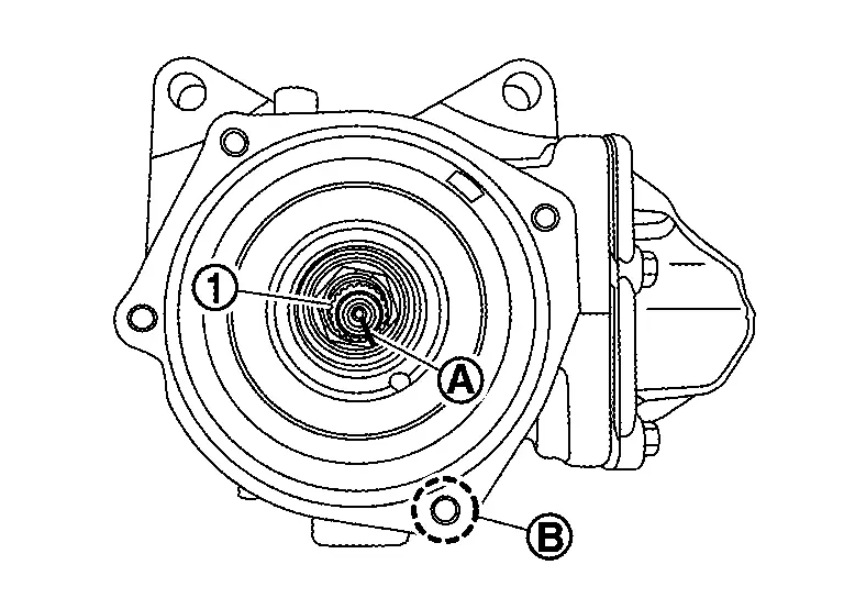
Remove side oil seal, using oil seal remover (commercial service tool).
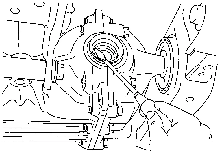
CAUTION:
Never damage gear carrier and rear cover.
INSTALLATION
Using the drift (A) (commercial service tool), drive side oil seal until it becomes flush with the gear carrier end.
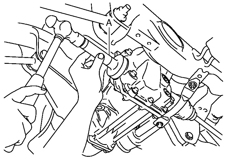
CAUTION:
-
Never reuse oil seal.
-
When installing, never incline oil seal.
-
Check that the oil seal lip is filled up with grease.
-
Apply gear oil lightly and evenly onto the outer circumference of oil seal.
Install rear drive shafts. Refer to Removal and Installation.
Refill gear oil to the final drive. Refer to Refilling.
Check the oil level and the oil leakage after installation. Refer to Inspection .
Electro-Hydraulic Coupling
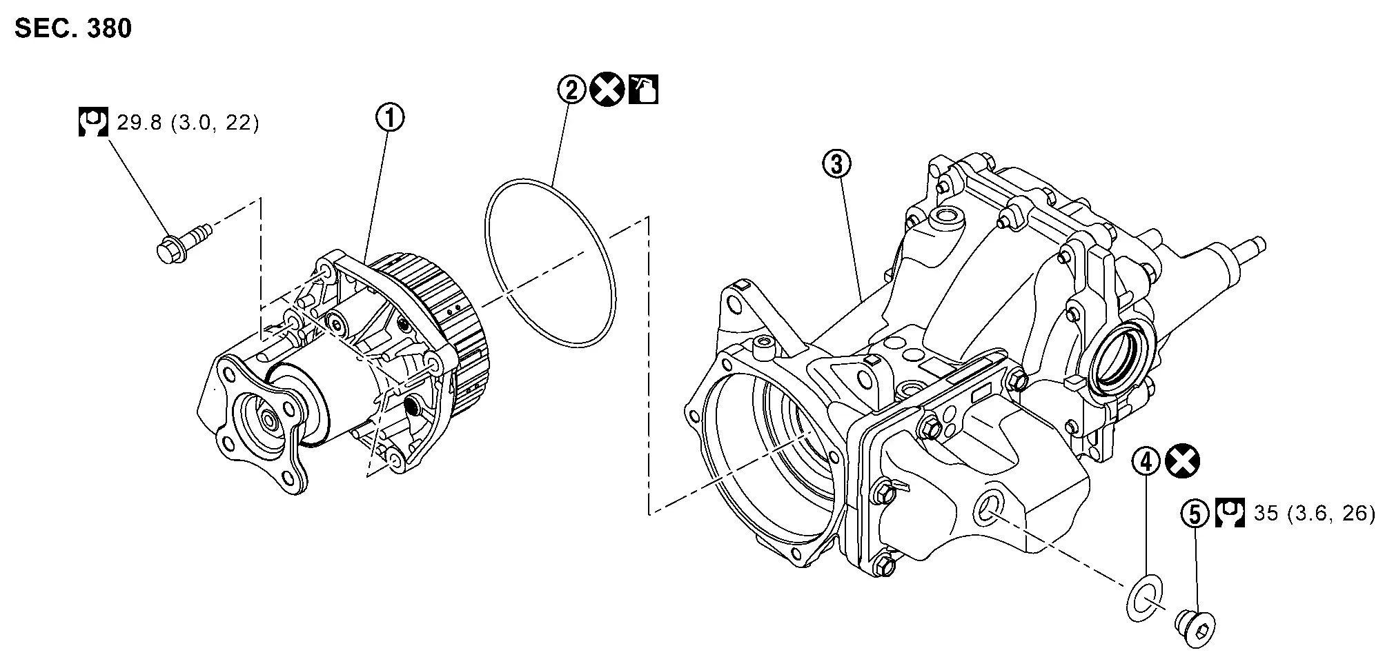
Exploded View
|
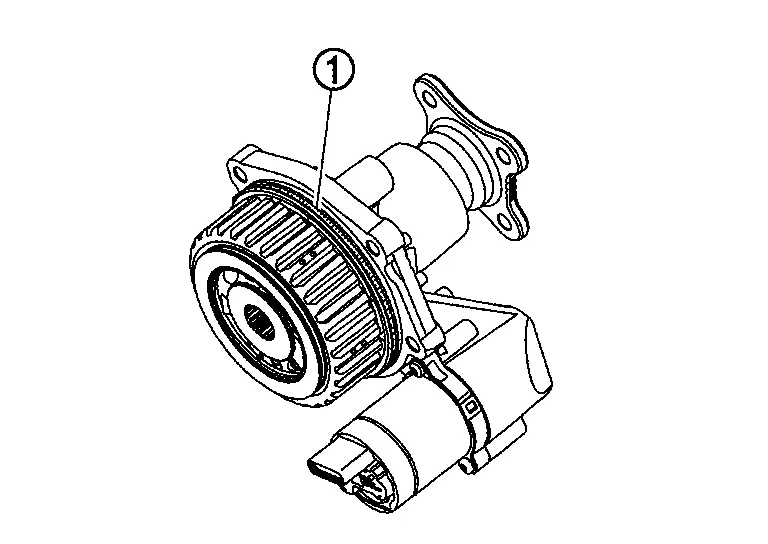
Electro-hydraulic coupling assembly | |
O-ring |  |
Rear final drive assembly |
 |
Gasket |  |
Filler plug | ||
 : N·m (kg-m, ft-lb) : N·m (kg-m, ft-lb) |
|||||
| : Always replace after every disassembly. |
|||||
| : Apply electro-hydraulic coupling oil (Genuine part). |
|||||
Removal and Installation
REMOVAL
 NOTE:
NOTE:
-
When replacing AWD control unit (integrated with actuator assembly of electro-hydraulic coupling assembly) or electro-hydraulic coupling assembly perform adjustment before removal. Refer to Adjustment.
-
Before replacing electro-hydraulic coupling due to vibration and/or noise when making low speed turns, refer to TSB to assist in proper diagnosis.
Remove propeller shaft from rear final drive companion flange. Refer to Removal and Installation (CVJ-CVJ-C).
NOTE:
Tie propeller shaft aside with a suitable strap.
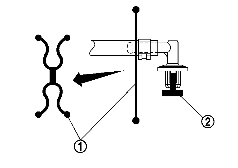
Disconnect harness connector of actuator assembly .
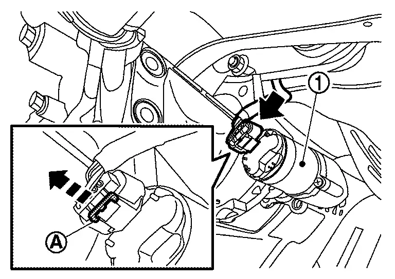
-
To disconnect harness connector, the lock tab
must be pulled outward.
Place a pan under electro-hydraulic coupling assembly mounting part.
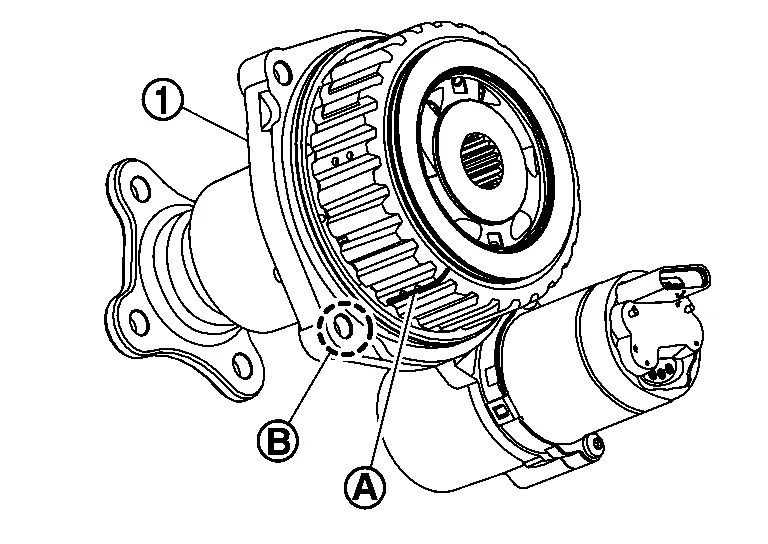
Remove electro-hydraulic coupling assembly from final drive assembly after removing electro-hydraulic coupling assembly mounting bolts.
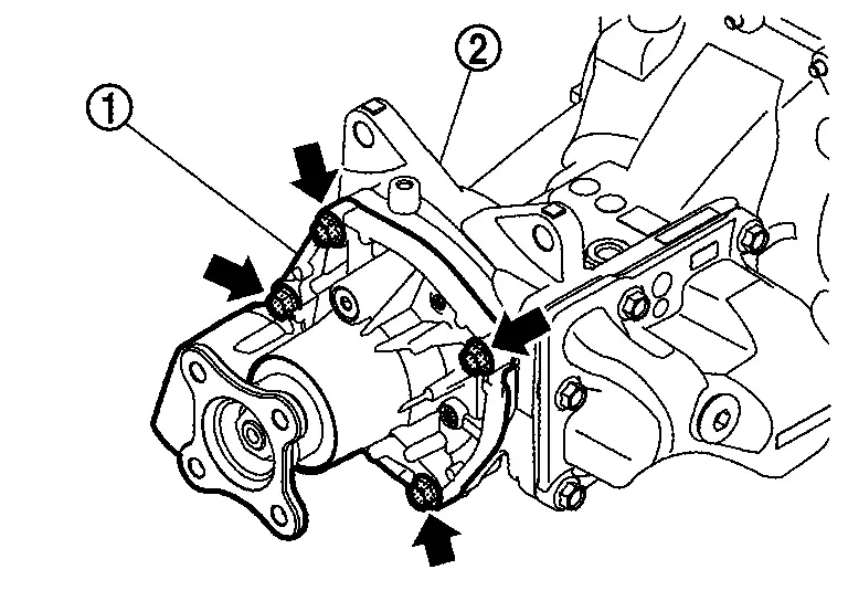
CAUTION:
Oil is drained from between electro-hydraulic coupling assembly and final drive assembly when removing.
-
If necessary, use cutout
to pry.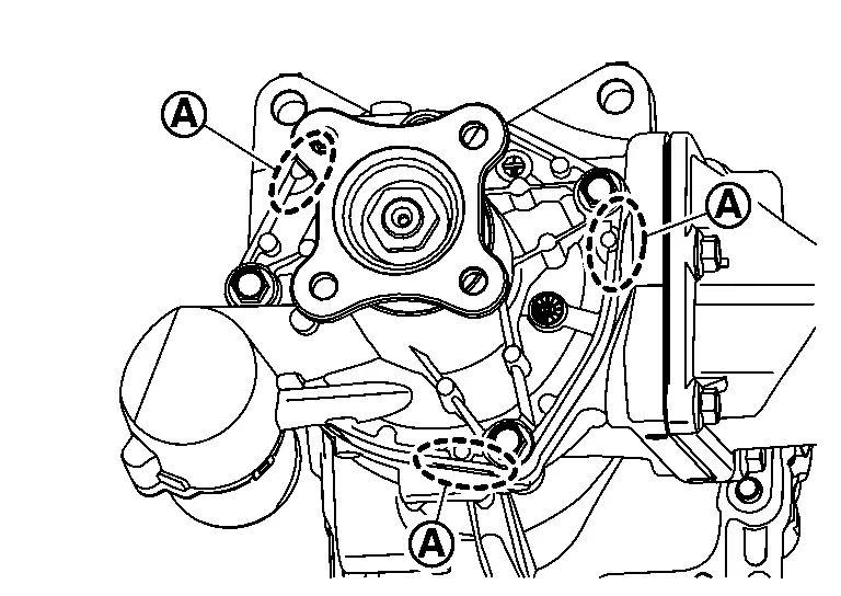
Remove O-ring from electro-hydraulic coupling assembly.
CAUTION:
-
Never use a tool.
-
Never damage electro-hydraulic coupling assembly.
INSTALLATION
CAUTION:
Be careful to place each part so that the contamination never stick to the drum surface flange during work.
Install O-ring to electro-hydraulic coupling assembly.
CAUTION:
-
Never reuse O-ring.
-
Apply electro-hydraulic coupling oil lightly and evenly onto O-ring.
-
When installing O-ring, never use a tool.
-
Never damage O-ring.
Locate aligning marking on tip of drive pinion . Rotate rear wheels until the aligning marking is aligned with the lower bolt hole  , as shown in figure.
Locate aligning marking on drum of electro-hydraulic coupling assembly and align it marking with the lower bolt hole , as shown in figure.
Install electro-hydraulic coupling assembly to final drive assembly .
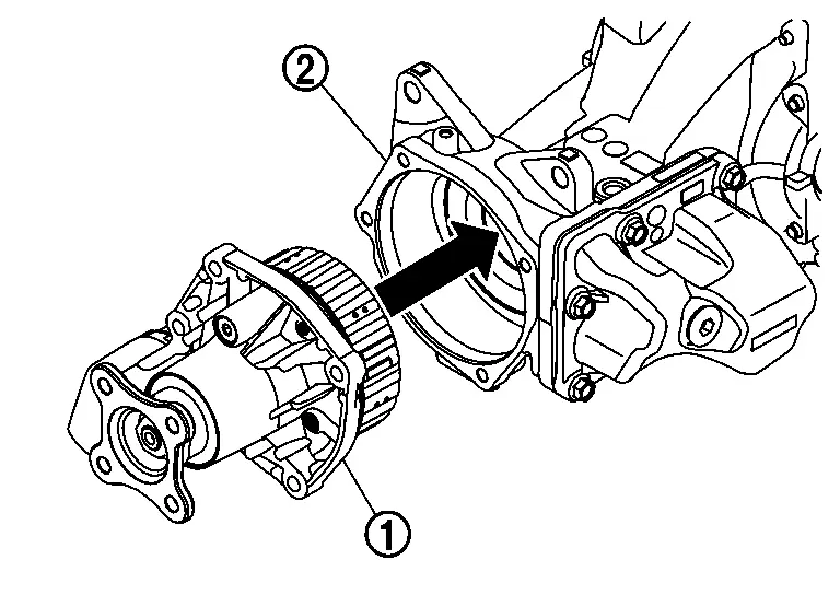
CAUTION:
Aligning marking on drum of electro-hydraulic coupling assembly and marking on tip of drive pinion.
-
Keep the aligning marking aligned with the lower bolt hole, as close as possible, while installing electro-hydraulic coupling assembly.
-
It may be necessary to slightly rotate companion flange during installation, to align the splines.
Tighten electro-hydraulic coupling assembly mounting bolts to the specified torque diagonally.
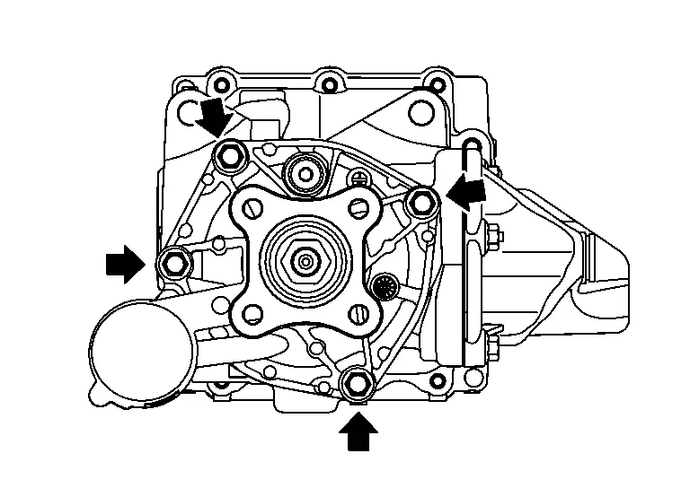
-
For tightening torque, refer to Exploded View.
CAUTION:
Check that electro-hydraulic coupling assembly is seated fully on final drive assembly before installing mounting bolts.
Connect harness connector of actuator assembly .
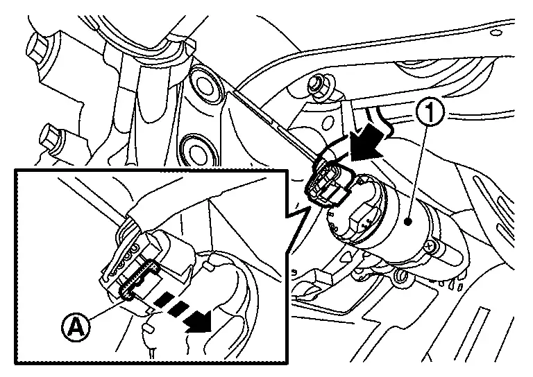
-
Push lock tab
inward to engage the connector.
Install propeller shaft to rear final drive companion flange. Refer to Removal and Installation (CVJ-CVJ-C).
Refill electro-hydraulic coupling oil. Refer to Adjustment.
When replacing AWD control unit (integrated with actuator assembly of electro-hydraulic coupling assembly) or electro-hydraulic coupling assembly perform adjustment after installation. Refer to Adjustment.
Adjustment
ADJUSTMENT BEFORE REMOVAL
AWD Control Unit Part Number Saving
When replacing AWD control unit (integrated with actuator assembly of electro-hydraulic coupling assembly) and electro-hydraulic coupling assembly, perform AWD control unit part number saving. Refer to Description.
ADJUSTMENT AFTER INSTALLATION
AWD Control Unit Programming
When replacing AWD control unit (integrated with actuator assembly of electro-hydraulic coupling assembly) and electro-hydraulic coupling assembly, perform programming to AWD control unit. Refer to Description.
Electro-Hydraulic Coupling Oil Filling, Air Bleeding and Initialize Oil Deterioration Level
When the electro-hydraulic coupling oil is drained, such as when replacing or removing/installing electro-hydraulic coupling component parts, the air bleeding and initialize oil deterioration level of electro-hydraulic coupling oil is required after fill with new electro-hydraulic coupling oil.
Fill with electro-hydraulic coupling oil following the instructions below.
Remove filler plug and gasket from coupling oil tank cover .
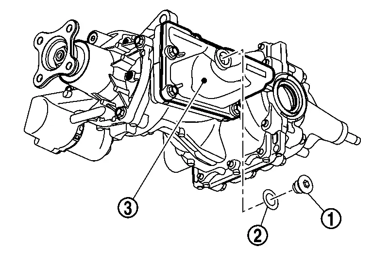
Fill with new electro-hydraulic coupling oil to specified amount.
| Specified amount | : Approx. 0.6  (1-1/4 US pt, 1 lmp pt) (1-1/4 US pt, 1 lmp pt) |
CAUTION:
-
Use LSC Transmission Fluid 12-301 or equivalent for electro-hydraulic coupling oil.
-
When using oil, allow the additives to diffuse well before use.
-
Oil that has been stored for 12 months can not be used.
NOTE:
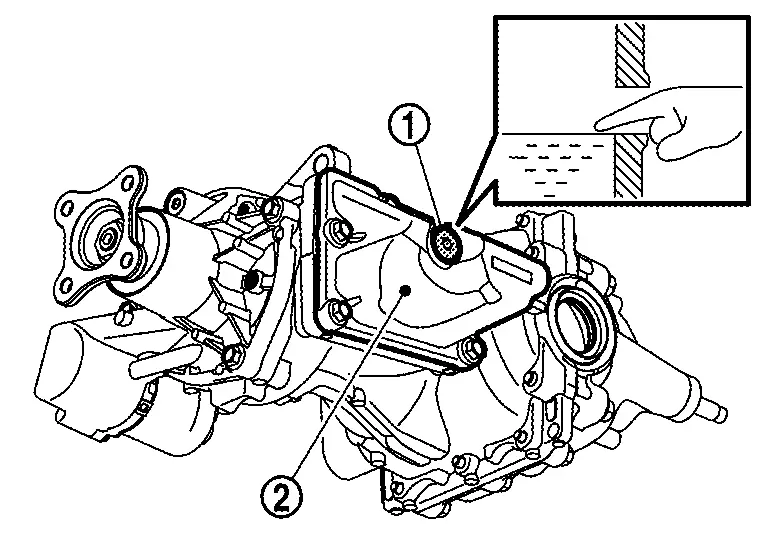
Oil level should be level with bottom of filler plug mounting hole.
Set the original gasket on filler plug, and install it to coupling oil tank cover.
NOTE:
The gasket will be replaced to new one at a later work.
Tighten filler plug to the specified torque. Refer to Exploded View.
Perform air bleeding and initialize oil deterioration level of electro-hydraulic coupling oil. Refer to Description.
Check oil level for electro-hydraulic coupling oil again.
NOTE:
The oil level may be reduced after air bleeding.
Check oil level from filler plug mounting hole as shown in the figure after removing filler plug and gasket from coupling oil tank cover .
CAUTION:
Turn the ignition switch OFF while checking oil level.
-
Oil level should be level with bottom of filler plug mounting hole. Add electro-hydraulic coupling oil if necessary.
CAUTION:
Never reuse gasket.
Tighten filler plug to the specified torque. Refer to Exploded View.Air Breather
Exploded View
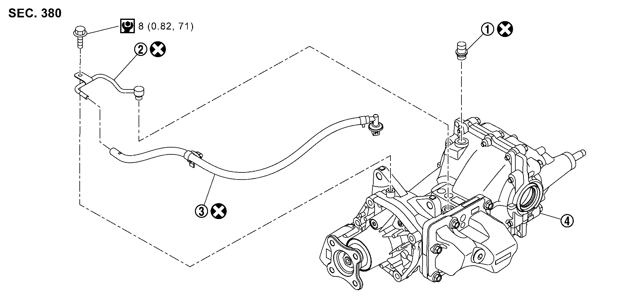
|
Breather assembly (1-way) | |
Coupling breather tube | |
Coupling breather hose assembly |
|
Rear final drive assembly | ||||
 : N·m (kg-m, in-lb) : N·m (kg-m, in-lb) |
|||||
| : Always replace after every disassembly. |
|||||
Removal and Installation
REMOVAL
Final Drive Side
Remove breather assembly (1-way) from rear final drive assembly.
-
When removing/installing breather assembly (1-way), remove rear final drive assembly from the Nissan Ariya vehicle. Refer to Removal and Installation.
Electro-hydraulic Coupling Side
Remove coupling breather hose assembly from coupling breather tube .
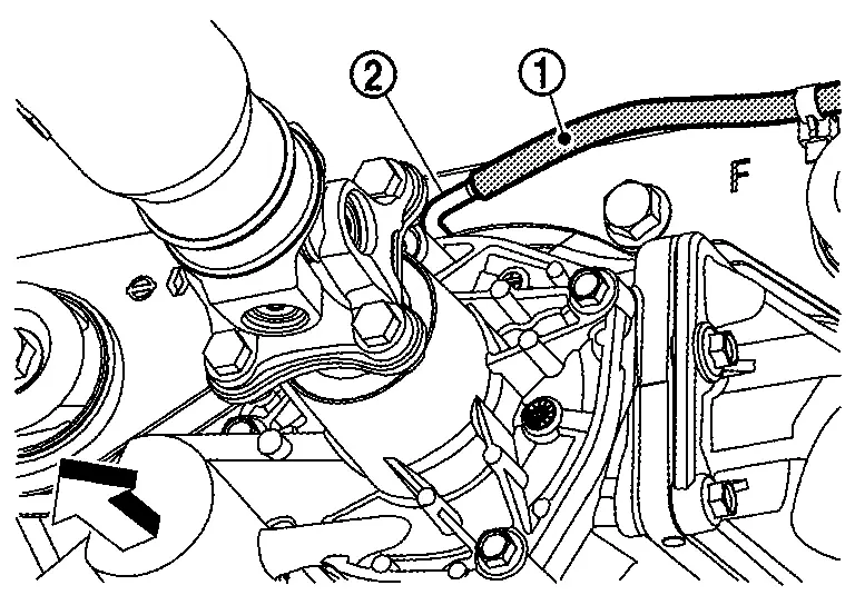
 |
: Nissan Ariya Vehicle front |
Remove clip of coupling breather hose assembly from final drive mounting bracket.
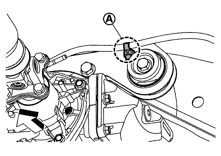
|
: Nissan Ariya Vehicle front |
Remove left rear tire. Refer to Removal and Installation.
Remove breather connector part from suspension member and remove coupling breather hose assembly .
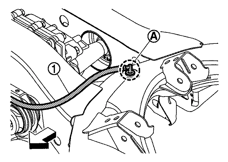
|
: Nissan Ariya Vehicle front |
Remove rear final drive assembly from the vehicle. Refer to Removal and Installation.
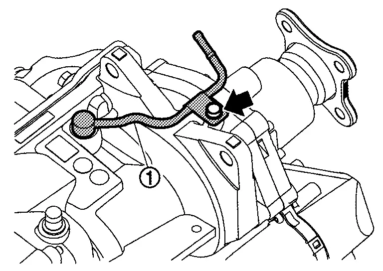
Remove coupling breather tube mounting bolt and remove coupling breather tube with O-ring.
INSTALLATION
Note the following, and install in the reverse order of removal.
-
For non-reusable parts, refer to Exploded View.
-
When installing air breather hose, make sure there are no pinched or restricted areas on air breather hose caused by bending or winding.
Final Drive Side
-
Breather assembly (1-way) must be press fitted until whole circumference of flange
reach the surface of rear cover.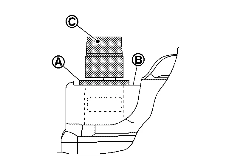
CAUTION:
Never press the cap
 .
.
Electro-hydraulic Coupling Side
-
When installing coupling breather tube, make sure there are no damage on O-ring.
NOTE:
In case of difficult insertion, apply electro-hydraulic coupling oil (genuine part) to O-ring.
-
When installing coupling breather hose assembly, loosely tighten bolt by hand. Secondly, tighten to the specified torque. Refer to Exploded View.
-
Securely install breather connector part
of coupling breather hose assembly to suspension member as shown in figure.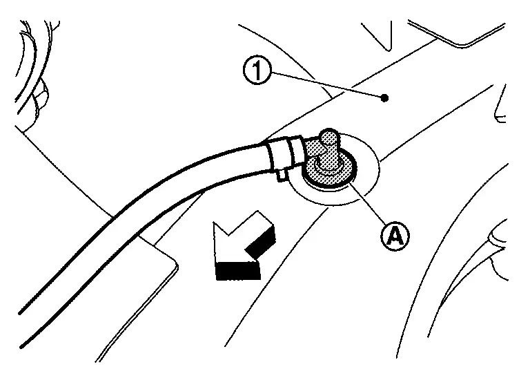
: Nissan Ariya Vehicle front -
Set coupling breather hose assembly
with the paint mark facing upward, and install it to coupling breather tube all the way to the bulged part .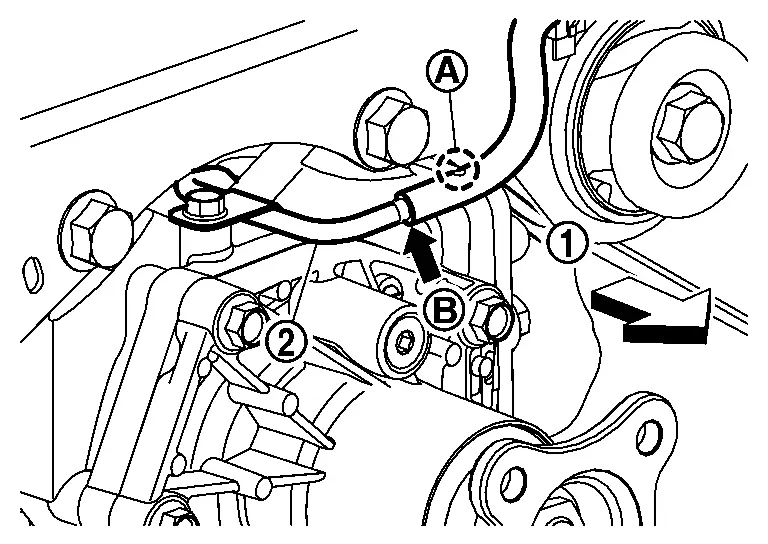
: Nissan Ariya Vehicle front
NOTE:
If fastener and rubber plug are attached, they are unnecessary and should be discarded.
Other materials:
Installing top tether strap
WARNING
Child restraint anchorages are designed only for correctly installed restraints. Never attach adult seat belts or other equipment to these points—doing so may damage the anchors and compromise safety.
Avoid hooking the tether strap on the seatback carpet. Always use the designated ...
P040c Egr Temperature Sensor
DTC Description
DTC DETECTION LOGIC DTC
CONSULT screen terms
(Trouble diagnosis content)
DTC detection condition
P040C
00
EGR TEMP SENSOR A
(EGR temperature sensor A circuit low)
Diagnosis condition
—
Signal (terminal)
—
Threshold
ECM detects that a vo ...
Precaution. Precautions
Precaution for Supplemental Restraint System (SRS) "AIR BAG" and "SEAT BELT PRE-TENSIONER"
The Supplemental Restraint System such as “AIR BAG” and “SEAT BELT
PRE-TENSIONER”, used along with a front seat belt, helps to reduce the
risk or severity of injury to the driver and front passeng ...