Nissan Rogue (T33) 2021-Present Service Manual: Rear Final Drive: R145 :: Unit Removal and Installation. Rear Final Drive Assembly
Rear Final Drive Assembly
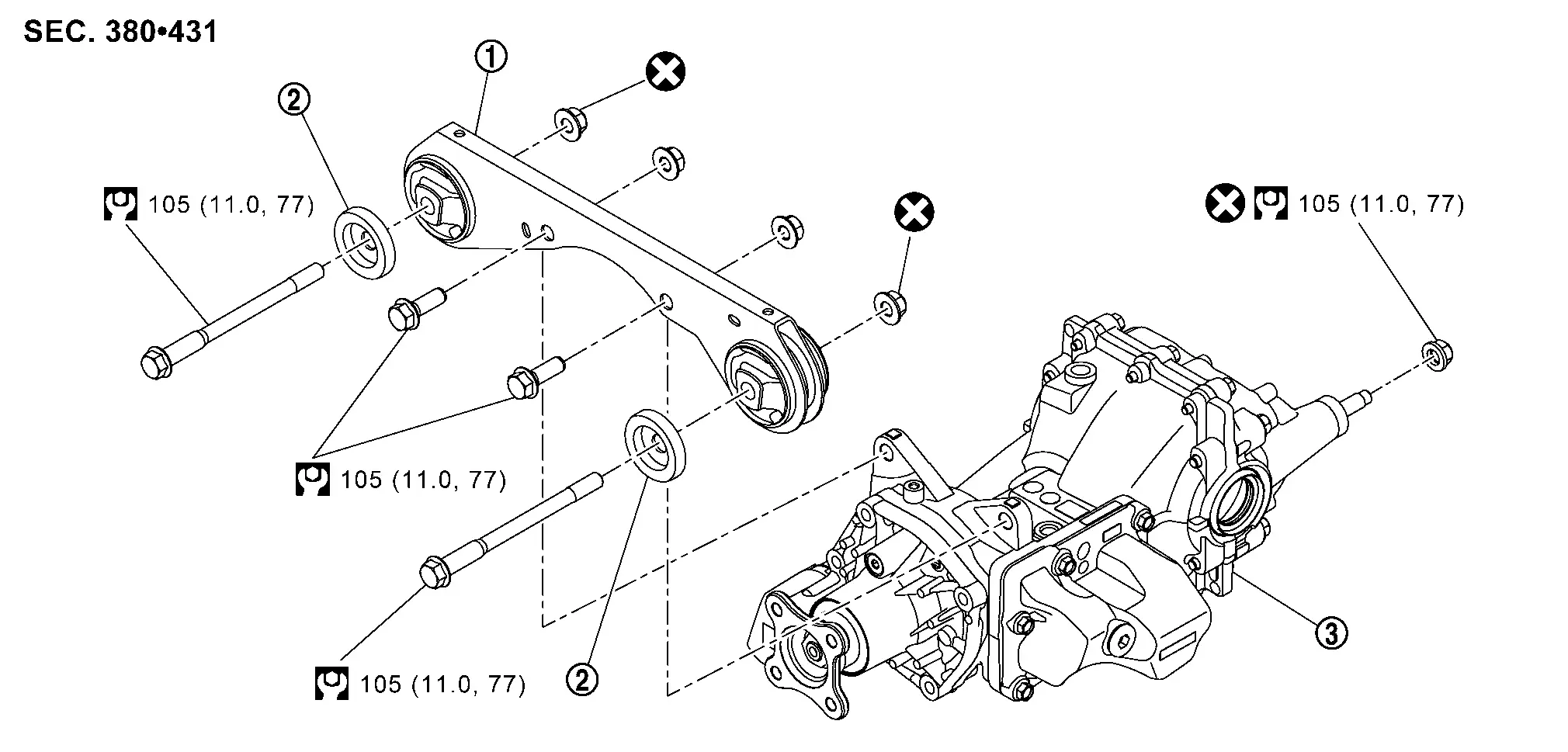
Exploded View
 |
Final drive mounting bracket |  |
Mounting stopper |  |
Rear final drive assembly |
 : N·m (kg-m, ft-lb) : N·m (kg-m, ft-lb) |
|||||
 : Always replace after every disassembly. : Always replace after every disassembly. |
|||||
Removal and Installation
REMOVAL
 NOTE:
NOTE:
-
When replacing AWD control unit (integrated with actuator assembly of electro-hydraulic coupling assembly) or electro-hydraulic coupling assembly after removing rear final drive assembly, perform adjustment before removal. Refer to Adjustment.
-
Before replacing electro-hydraulic coupling due to vibration and/or noise when making low speed turns, refer to TSB to assist in proper diagnosis.
Remove rear drive shaft. Refer to Removal and Installation.
CAUTION:
Oil may leak from the opening. Use cap and/or plug to prevent leakage.
Remove propeller shaft from rear final drive assembly. Refer to Removal and Installation (CVJ-CVJ-C).
Disconnect harness connector of actuator assembly (1).
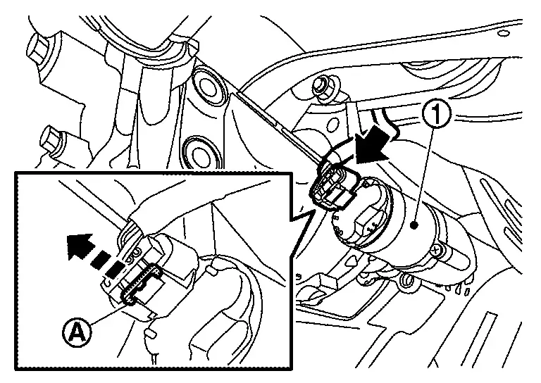
-
To disconnect harness connector, the lock tab (A) must be pulled outward.
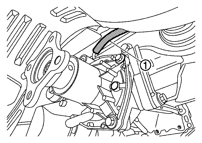
Remove air breather hoses (1) from electro-hydraulic coupling assembly. Refer to Removal and Installation.
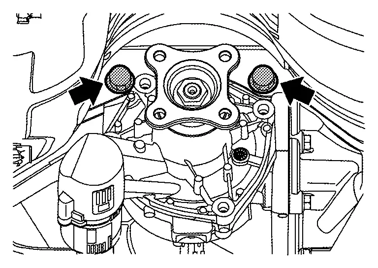
Set a suitable jack to rear final drive assembly.
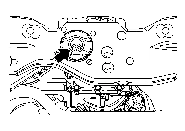
Remove rear final drive assembly mounting nut at rear suspension member.
Remove bolts and nuts engaging final drive mounting bracket with rear final drive assembly.
CAUTION:
Secure rear final drive assembly to suitable jack.
Remove rear final drive assembly.
CAUTION:
Secure rear final drive assembly to suitable jack while removing it.
Remove fuel tank. Refer to Removal and Installation.
Remove bolts and nuts engaging final drive mounting bracket with rear suspension member.
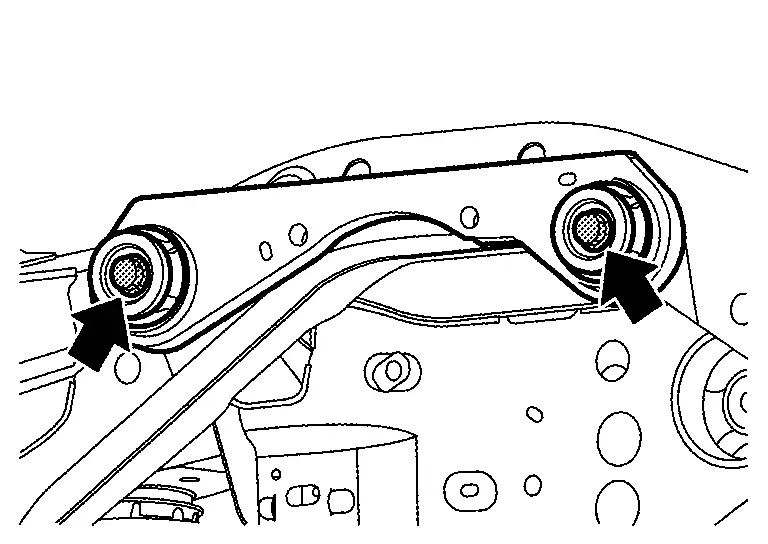
Remove final drive mounting bracket and mounting stoppers.
INSTALLATION
Note the following, install in the reverse order of removal.
-
For non-reusable parts, refer to Exploded View.
-
For each tightening torque, refer to Exploded View.
-
When oil leaks while removing/installing final drive assembly, check oil level after the installation. Refer to Inspection.
-
When replaced rear final drive assembly, AWD control unit (integrated with actuator assembly of electro-hydraulic coupling assembly) or electro-hydraulic coupling assembly was changed, perform adjustment after installation. Refer to Adjustment.
Other materials:
High Pressure Fuel Pump
Component Function Check
CHECK HIGH PRESSURE FUEL PUMP FUNCTION
With CONSULT
Start engine.
Select âFUEL PRES SEN Vâ in âDATA MONITORâ mode of âENGINEâ using
CONSULT and check the indication as per the following conditions.
Monitor item Condition Indication
FUEL PRES ...
Protection contre la corrosion
Facteurs de corrosion les plus courants
Accumulation de poussiÃĻre humide, de sable et de dÃĐbris dans les panneaux de carrosserie, les orifices et les zones peu ventilÃĐes.
Dommages de la peinture ou des revÊtements protecteurs causÃĐs par des projections de gravillons ou de petits accidents ...
C106b-64 Stop Lamp Sw
DTC Description
DTC DETECTION LOGIC DTC No.
CONSULT screen terms
(Trouble diagnosis content) DTC detection condition
C106B
64
Stop lamp SW
(Stop lamp switch)
Diagnosis condition
When ignition switch is ON.
When the power supply voltage is normal.
Signal (ter ...