Nissan Rogue (T33) 2021-Present Service Manual: Precaution :: Precautions
Precautions for Removing Battery Terminal
-
With the adoption of Auto ACC function, ACC power is automatically supplied by operating the Intelligent Key or remote keyless entry or by opening/closing the driver side door. In addition, ACC power is supplied even after the ignition switch is turned to the OFF position, i.e. ACC power is supplied for a certain fixed time.
-
When disconnecting the 12V battery terminal, turn off the ACC power before disconnecting the 12V battery terminal, observing тАЬHow to disconnect 12V battery terminalтАЭ described below.
 NOTE:
NOTE:
Some ECUs operate for a certain fixed time even after ignition switch is turned OFF and ignition power supply is stopped. If the battery terminal is disconnected before ECU stops, accidental DTC detection or ECU data damage may occur.
-
For Nissan Ariya vehicles with the 2-batteries, be sure to connect the main battery and the sub battery before turning ON the ignition switch.
NOTE:
If the ignition switch is turned ON with any one of the terminals of main battery and sub battery disconnected, then DTC may be detected.
-
After installing the 12V battery, always check "Self Diagnosis Result" of all ECUs and erase DTC.
NOTE:
The removal of 12V battery may cause a DTC detection error.
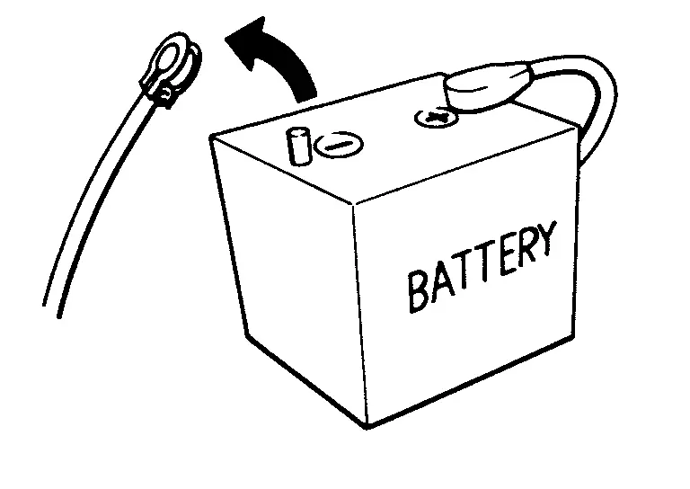
HOW TO DISCONNECT 12V BATTERY TERMINAL
Disconnect 12V battery terminal according to instruction described below.
-
Open the hood.
-
Turn ignition switch to the ON position.
-
Turn ignition switch to the OFF position with the driver side door opened.
-
Get out of the Nissan Ariya vehicle and close the driver side door.
-
Wait at least 3 minutes.
CAUTION:
While waiting, never operate the Nissan Ariya vehicle such as locking, opening, and closing doors. Violation of this caution results in the activation of ACC power supply according to the Auto ACC function.
-
Remove 12V battery terminal.
CAUTION:
After installing 12V battery, always check self-diagnosis results of all ECUs and erase DTC.
Precaution for Supplemental Restraint System (SRS) "AIR BAG" and "SEAT BELT PRE-TENSIONER"
The Supplemental Restraint System such as тАЬAIR BAGтАЭ and тАЬSEAT BELT PRE-TENSIONERтАЭ, used along with a front seat belt, helps to reduce the risk or severity of injury to the driver and front passenger for certain types of collision.
Information necessary to service the system safely is included in the тАЬSRS AIR BAGтАЭ and тАЬSEAT BELTтАЭ of this Service Manual.
WARNING:
Always observe the following items for preventing accidental activation.
-
To avoid rendering the SRS inoperative, which could increase the risk of personal injury or death in the event of a collision that would result in air bag inflation, it is recommended that all maintenance and repair be performed by an authorized NISSAN/INFINITI dealer.
-
Improper repair, including incorrect removal and installation of the SRS, can lead to personal injury caused by unintentional activation of the system. For removal of Spiral Cable and Air Bag Module, see тАЬSRS AIR BAGтАЭ.
-
Never use electrical test equipment on any circuit related to the SRS unless instructed to in this Service Manual. SRS wiring harnesses can be identified by yellow and/or orange harnesses or harness connectors.
PRECAUTIONS WHEN USING POWER TOOLS (AIR OR ELECTRIC) AND HAMMERS
WARNING:
Always observe the following items for preventing accidental activation.
-
When working near the Air Bag Diagnosis Sensor Unit or other Air Bag System sensors with the ignition/power switch ON or engine running, never use air or electric power tools or strike near the sensor(s) with a hammer. Heavy vibration could activate the sensor(s) and deploy the air bag(s), possibly causing serious injury.
-
When using air or electric power tools or hammers, always switch the ignition/power switch OFF, disconnect the 12V battery or batteries, and wait at least 3 minutes before performing any service.
Service
-
Never use electrical test equipment to check SRS circuits unless instructed to in this Service Manual.
-
Before servicing the SRS, ignition switch OFF, disconnect battery negative terminal and wait 3 minutes or more.
For approximately 3 minutes after the cables are removed, it is still possible for the air bag and seat belt pre-tensioner to deploy. Therefore, never work on any SRS connectors or wires until at least 3 minutes have passed.
-
Diagnosis sensor unit must always be installed with their arrow marks тАЬтЗРтАЭ pointing towards the front of the Nissan Ariya vehicle for proper operation. Also check diagnosis sensor unit for cracks, deformities or rust before installation and replace as required.
-
The spiral cable must be aligned with the neutral position since its rotations are limited. Never turn steering wheel and column after removal of steering gear.
-
Handle air bag module carefully. Always place driver and front passenger air bag modules with the pad side facing upward and seat mounted front side air bag module standing with the stud bolt side facing down.
-
Conduct self-diagnosis to check entire SRS for proper function after replacing any components.
-
After air bag inflates, the front instrument panel assembly should be replaced if damaged.
-
Always replace instrument panel pad following front passenger air bag deployment.
-
Never solder the harness when making repairs. Check that harness is not pinched and that there is no contact with other components.
-
Never allow harness to come in contact with oil, grease, waste oil, or water.
-
Never insert foreign materials, such as a screwdriver, into the harness connector. (This is to prevent accidental activation caused by static electricity.)
-
Always use CONSULT or SRS air bag warning lamp to perform the circuit diagnosis. (Never use an electric tester such as a circuit tester.)
Other materials:
Automatic Air Conditioning. Removal and Installation
A/c Switch Assembly
Exploded View
A/C switch assembly
Center ventilator finisher
: Pawl
: Nissan Ariya Vehicle front
Removal and Installation
REMOVALRemove center ventilator finisher. Refer to Removal and Installation.
Remove A/C switch assembly fixi ...
Driver Controls. Horn
Precaution :: Precautions
Precaution for Supplemental Restraint System (SRS) "AIR BAG" and "SEAT BELT PRE-TENSIONER"
The Supplemental Restraint System such as тАЬAIR BAGтАЭ and тАЬSEAT BELT
PRE-TENSIONERтАЭ, used along with a front seat belt, helps to reduce the
risk or severity of injury to t ...
Dtc/circuit Diagnosis. U0075-00 Communication Bus C Off
DTC Description
DTC DETECTION LOGIC DTC No.
CONSULT screen items
(Trouble diagnosis content) DTC Detection Condition
U0075-00
Control module comm Bus C Off
(Control module communication Bus C Off)
Diagnosis condition
Ignition switch ON
Signal (terminal)
CAN communication s ...