Nissan Rogue (T33) 2021-Present Service Manual: Periodic Maintenance :: Chassis Maintenance
Exhaust System
Inspection
Check exhaust pipes, muffler, and mounting for improper attachment, leakage, cracks, damage or deterioration.
-
If anything is found, repair or replace damaged parts.
Cvt Fluid: Ge0f14a
Inspection
-
Check transaxle surrounding area (oil seal and plug etc.) for fluid leakage.
-
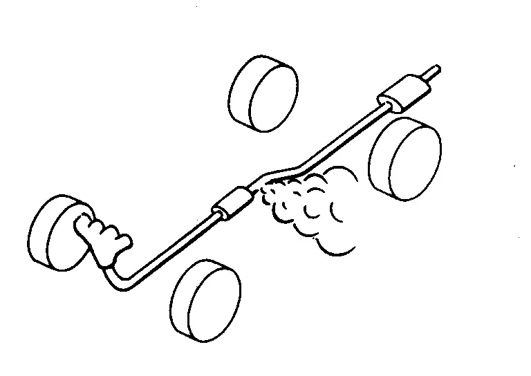
If transaxle appears to have oil seepage or a leak, follow the steps below to assist in a correct diagnosis.
Thoroughly clean off the area of the suspected leak.
Insert 1 fluid ounce of fluorescent oil dye into CVT.
| Tool number | : — (NI-52990) |
-
When removing CVT fluid charging pipe cap, use CVT charge pipe cap release tool [SST: — (NI-52611)].
CAUTION:
Never reuse CVT fluid charging pipe cap.
Drive Nissan Ariya vehicle for a minimum of 10 minutes.
Inspect for leaks with A/C Dye Kit (Refrigerant dye leak detection kit).
| Tool number | : — (NI-43926) |
 NOTE:
NOTE:
-
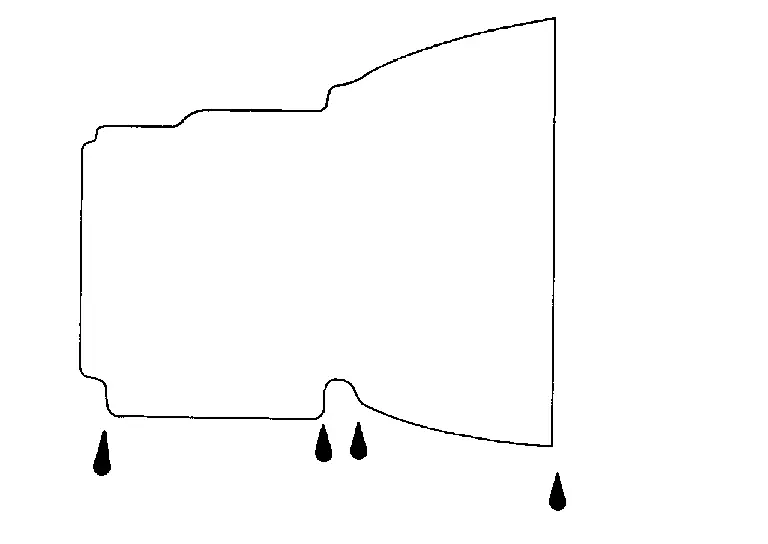
Corrosion protection chemicals or assembly lubricants may cause dust to accumulate (gather) on the transaxle and have the appearance of an oil leak. Neither of these requires corrective action.
-
If no fluorescent oil trace/leak is found, no action is necessary.
-
If fluorescent oil trace/leak is found repair or replace damaged parts and adjust CVT fluid level. Refer to Adjustment.
Replacement
| CVT fluid and fluid capacity | : Refer to Fluids and Lubricants. |
CAUTION:
-
Always use shop paper. Never use shop cloth.
-
Replace a drain plug gasket with new ones at the final stage of the operation when installing.
-
Use caution when looking into the drain hole as there is a risk of dripping fluid entering the eye.
-
After replacement, always perform CVT fluid leakage check.
Select “Data Monitor” in “TRANSMISSION” using CONSULT.
Select “FLUID TEMP” and confirm that the CVT fluid temperature is 40°C (104°F) or less.
Check that the shift position is in the “P” position, then completely engage the parking brake.
Lift up the Nissan Ariya vehicle.
Remove the drain plug and drain the CVT fluid from the oil pan. Refer to Exploded View.
Install the drain plug to oil pan.
CAUTION:
Drain plug gasket use the old one.
Remove the overflow plug  from converter housing.

| : Nissan Ariya Vehicle front |
Install the charging pipe set [SST: KV311039S0 (—)] with CVT stand pipe adapter kit [SST: — (NI-52584)](A) into the overflow plug hole.
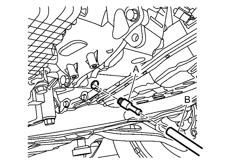
| B | : ATF charger hose |
CAUTION:
Tighten the charging pipe by hand.
Install the ATF changer hose to the charging pipe.
CAUTION:
Press the ATF changer hose all the way onto the charging pipe until it stops.
Fill approximately 3 liter (3-1/8 US qt, 2-5/8 lmp qt) of the CVT fluid.
Remove the ATF changer hose and charging pipe, then install the overflow plug.
NOTE:
Perform this work quickly because CVT fluid leaks.
Lower the Nissan Ariya vehicle.
Start the engine.
While depressing the brake pedal, shift to the entire position from “P” to “D”, and shift to the “P” position.
NOTE:
Hold the lever at each position for 5 seconds.
Check that the CONSULT “Data Monitor” in “FLUID TEMP” is 35°C (95°F) to 45°C (113°F).
Stop the engine.
Lift up the Nissan Ariya vehicle.
Remove the drain plug, and then drain CVT fluid from oil pan.
Repeat steps 8 to 18 (one time).
Tighten the drain plug to the specified torque. Refer to Exploded View.
Remove the overflow plug.
Install the charging pipe set [SST: KV311039S0 (—)] with CVT stand pipe adapter kit [SST: — (NI-52584)] into the overflow plug hole.
CAUTION:
Tighten the charging pipe by hand.
Install the ATF changer hose to the charging pipe.
CAUTION:
Press the ATF changer hose all the way onto the charging pipe until it stops.
Fill approximately 3.5 litter (3-3/4 US qt, 3-1/8 lmp qt) of the CVT fluid.
Remove the ATF changer hose and charging pipe, then install the overflow plug.
NOTE:
Perform this work quickly because CVT fluid leaks.
Lower the Nissan Ariya vehicle.
Start the engine.
While depressing the brake pedal, shift to the entire position from “P” to “D”, and shift to the “P” position.
NOTE:
Hold the lever at each position for 5 seconds.
Check that the CONSULT “Data Monitor” in “FLUID TEMP” is 35°C (95°F) to 45°C (113°F).
Lift up the Nissan Ariya vehicle.
Remove the overflow plug and confirm that the CVT fluid is drained from the overflow plug hole.
CAUTION:
Perform this work with the Nissan Ariya vehicle idling.
NOTE:
If the CVT fluid is not drained, refer to “Adjustment” and refill with the CVT fluid. Refer to Adjustment.
When the flow of CVT fluid slows to a drip, tighten the overflow plug to the specified torque. Refer to Exploded View.
CAUTION:
Never reuse O-ring.
Lower the Nissan Ariya vehicle.
Select “Data Monitor” in “TRANSMISSION” using CONSULT.
Select “CONFORM CVTF DETERIORTN”.
Select “Erase”.
Stop the engine.
Adjustment
| CVT fluid and fluid capacity | : Refer to Fluids and Lubricants. |
CAUTION:
-
During adjustment of the CVT fluid level, check CONSULT so that the oil temperature may be maintained from 35 to 45°C (95 to 113°F).
-
Maintain specified engine idle speed during CVT fluid level adjustment. Refer to IDLE SPEED : Periodic Maintenance.
-
Use caution when looking into the drain hole as there is a risk of dripping fluid entering the eye.
Check that the shift position is in the “P” position, then completely engage the parking brake.
Start the engine.
Adjust the CVT fluid temperature to be approximately 40°C (104°F).
NOTE:
The CVT fluid is largely affected by temperature. Therefore be sure to use CONSULT and check the “FLUID TEMP” under “TRANSMISSION” in “Data Monitor” while adjusting.
While depressing the brake pedal, shift to the entire position from “P” to “D”, and shift to the “P” position.
NOTE:
Hold the lever at each position for 5 seconds.
Lift up the Nissan Ariya vehicle.
Check that there is no CVT fluid leakage.
Remove the overflow plug from converter housing.
 |
: Nissan Ariya Vehicle front |
Install the charging pipe set [SST: KV311039S0 (—)] with CVT stand pipe adapter kit [SST: — (NI-52584)] (A) into the overflow plug hole.
| B: | : ATF charger hose |
CAUTION:
Tighten the charging pipe by hand.
Install the ATF changer hose to the charging pipe.
CAUTION:
Press the ATF changer hose all the way onto the charging pipe until it stops.
Fill approximately 0.5 liter (1/2 US qt, 1/2 lmp qt) of the CVT fluid.
Remove the ATF changer hose from the charging pipe, and check that the CVT fluid drains out from the charging pipe. If it does not drain out, perform charging again.
CAUTION:
Perform this work with the Nissan Ariya vehicle idling.
When the flow of CVT fluid slows to a drip, remove the charging pipe from the converter housing.
Tighten the overflow plug to the specified torque. Refer to Exploded View.
CAUTION:
Never reuse O-ring.
Lower the Nissan Ariya vehicle.
Stop the engine.
Refilling
| CVT fluid and fluid capacity | : Refer to Fluids and Lubricants. |
CAUTION:
-
Always use shop paper. Never use shop cloth.
-
Use caution when looking into the drain hole as there is a risk of dripping fluid entering the eye.
-
After replacement, always perform CVT fluid leakage check.
-
Use only Genuine CVT fluid. Using transmission fluid other than Genuine CVT fluid will damage the CVT, which is not covered by the warranty.
Check that the shift position is in the “P” position, then completely engage the parking brake.
Lift up the Nissan Ariya vehicle.
Remove the overflow plug from converter housing.
|
: Nissan Ariya Vehicle front |
Install the charging pipe set [SST: KV311039S0 (—)] with CVT stand pipe adapter kit [SST: — (NI-52584)] (A) into the overflow plug hole.
| B: | : ATF charger hose |
CAUTION:
Tighten the charging pipe by hand.
Install the ATF changer hose to the charging pipe.
CAUTION:
Press the ATF changer hose all the way onto the charging pipe until it stops.
Fill the CVT fluid. For the amount of CVT fluid to refill, refer to the following table.
| Work | Amount of CVT fluid to refill |
| When draining CVT fluid only | Approx. 3.5 litter (3-3/4 US qt, 3-1/8 lmp qt) |
| When removing/installing oil pan without control valve removing | Approx. 4.2 litter (4-1/2 US qt, 3-3/4 lmp qt) |
| Replacement of control valve | Approx. 5.0 litter (5-1/2 US qt, 4-3/8 lmp qt) |
| Replacement of torque converter | Approx. 1.5 litter (1-5/8 US qt, 1-3/8 lmp qt) |
| Replacement of pulley and belt assembly and control valve | Refer to Fluids and Lubricants. |
Remove the ATF changer hose and charging pipe, then install the overflow plug.
NOTE:
Perform this work quickly because CVT fluid leaks.
Lower the Nissan Ariya vehicle.
Start the engine and let it idle for 2 minutes.
While depressing the brake pedal, shift to each position from “P” to “D (or L or Ds)”, and then shift to “P” position.
NOTE:
Hold the lever at each position for 5 seconds.
Check that the CONSULT “Data Monitor” in “FLUID TEMP” is 35°C (95°F) to 45°C (113°F).
Lift up the Nissan Ariya vehicle.
Remove the overflow plug and confirm that the CVT fluid is drained from the overflow plug hole.
CAUTION:
Perform this work with the Nissan Ariya vehicle idling.
NOTE:
If the CVT fluid is not drained, refer to “Adjustment” and refill with the CVT fluid. Refer to Adjustment.
When the flow of CVT fluid slows to a drip, tighten the overflow plug to the specified torque. Refer to Exploded View.
CAUTION:
Never reuse O-ring.
Lower the Nissan Ariya vehicle.
Select “Work Support” in “TRANSMISSION” using CONSULT.
Select “CONFORM CVTF DETERIORTN”.
Select “Erase”.
Stop the engine.
Transfer Oil
Inspection
OIL LEAKAGE
-
Remove engine under cover during working. Refer to Exploded View.
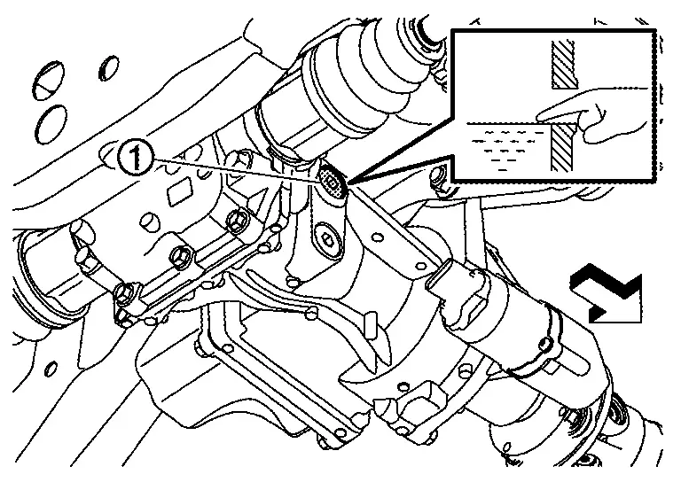
Check transfer surrounding area (oil seal, drain plug, and filler plug etc.) for oil leakage.
OIL LEVEL
-
Remove engine under cover during working. Refer to Exploded View.
Check oil level from filler plug mounting hole as shown in the figure, after removing filler plug and gasket from transfer assembly.
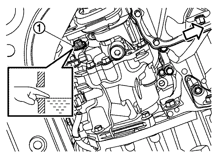
| : Nissan Ariya Vehicle front |
CAUTION:
Place the ignition switch OFF while checking oil level.
-
Oil level should be level with bottom of filler plug mounting hole. Add transfer oil if necessary. Refer to Refilling.
Set a gasket on filler plug and install it on transfer assembly.
CAUTION:
Never reuse gasket.
Tighten filler plug to the specified torque. Refer to Exploded View(KR15DDT).
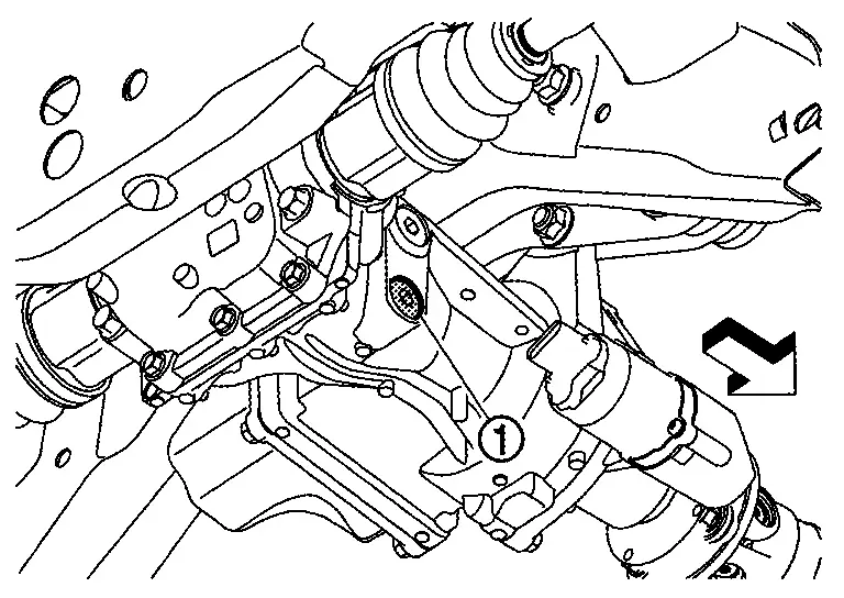
Draining
-
Remove engine under cover during working. Refer to Exploded View.
Run the vehicle to warm up the transfer unit sufficiently.
Stop the vehicle and place the ignition switch OFF.
Remove drain plug (1) and gasket.
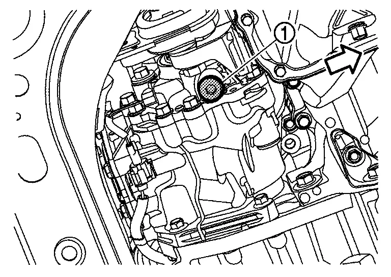
| : Nissan Ariya Vehicle front |
Drain transfer oil.
NOTE:
Removing filler plug can make the work easier.
Set a gasket on drain plug and install it to transfer assembly.
CAUTION:
Never reuse gasket.
Tighten drain plug to the specified torque. Refer to Exploded View (KR15DDT).
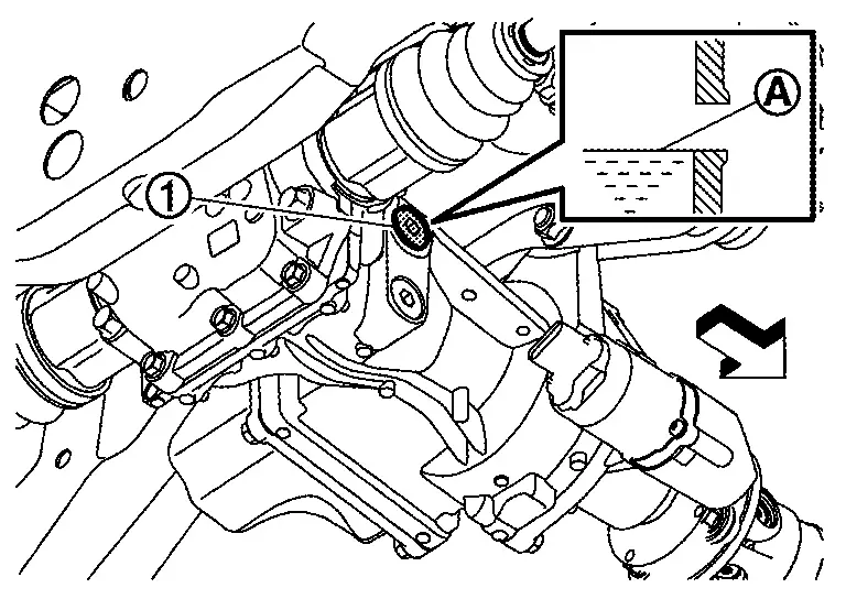
Refilling
-
Remove engine under cover during working. Refer to Exploded View.
Fill with new transfer oil until oil level reaches the specified level  near filler plug mounting hole, after removing filler plug and gasket from transfer assembly.
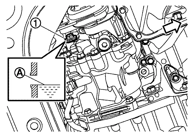
| : Nissan Ariya Vehicle front |
| Recommended oil and capacity | : Refer to Fluids and Lubricants. |
Rotate the propeller shaft or drive shafts slowly by hand to penetrate the transfer oil inside of transfer assembly.
Leave the Nissan Ariya vehicle for 3 minutes, and check the oil level again.
Set a gasket on filler plug, and install it to transfer assembly.
CAUTION:
Never reuse gasket.
Tighten filler plug to the specified torque. Refer to Exploded View(KR15DDT).
Rear Propeller Shaft: Cvj-Cvj-C
Inspection
LOOSENESS OF CONNECTED PART
Check each fixing bolt and nut for looseness using torque wrench. For each tightening torque, refer to Exploded View.
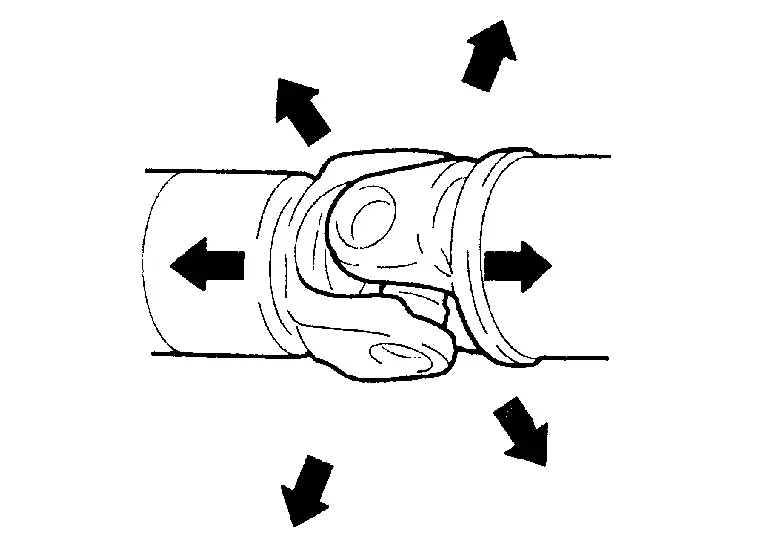
BACKLASH OF JOINT PART
Move the joint of propeller shaft up and down and from side to side (axial direction of shaft and right angle to shaft) to check that the joint has no backlash. If the joint has a malfunction, remove propeller shaft and perform inspection.
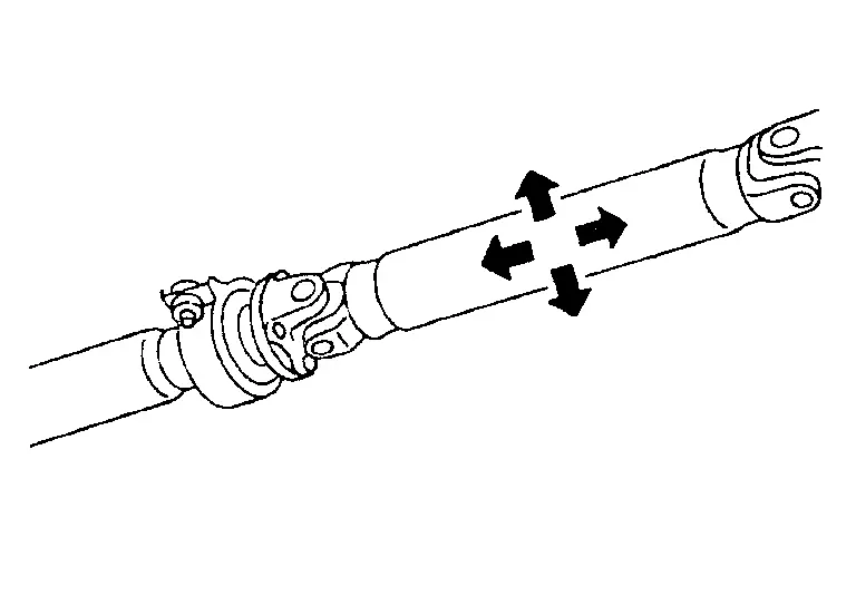
BACKLASH OF CENTER BEARING
Move the shaft near center bearing up and down and from side to side (axial direction of shaft and right angle to shaft) to check that the bearing has no backlash. If the bearing has a malfunction, remove propeller shaft and perform inspection.
APPEARANCE AND NOISE
-
Check the propeller shaft tube surface for dents or cracks. If malfunction is detected, replace propeller shaft assembly.
-
If center bearing is noisy or damaged, replace propeller shaft assembly.
VIBRATION
If vibration is present at high speed, adjust the propeller shaft phase first.
Check the propeller shaft for bend and damage. If damaged, replace propeller shaft assembly.
Perform a cruise test drive to check the propeller shaft for runout. If vibration occurs, separate propeller shaft at final drive companion flange; then change the phase between companion flange and propeller shaft by the one bolt hole at a time and install propeller shaft.
If vibration is still detected, measure propeller shaft runout after removing it. Refer to Inspection.
Rear Differential Gear Oil
Inspection
OIL LEAKAGE
Make sure that oil is not leaking from final drive assembly or around it.
OIL LEVEL
Check oil level from filler plug mounting hole as shown in the figure after removing filler plug and gasket from final drive assembly.
| : Nissan Ariya Vehicle front |
CAUTION:
Place the ignition switch OFF while checking oil level.
-
Oil level should be level with bottom of filler plug mounting hole. Add gear oil if necessary. Refer to Refilling.
Set a gasket on filler plug and install it on final drive assembly.
CAUTION:
Never reuse gasket.
Tighten filler plug to the specified torque. Refer to Exploded View.
Draining
Turn the ignition switch OFF.
Remove drain plug and gasket.
| : Nissan Ariya Vehicle front |
Drain gear oil.
NOTE:
Removing filler plug can make the work easier.
Set a gasket on drain plug and install it to final drive assembly.
CAUTION:
Never reuse gasket.
Tighten drain plug to the specified torque. Refer to Exploded View.
Refilling
Remove filler plug and gasket. Then fill with new gear oil until oil level reaches the specified level near filler plug mounting hole.
| : Nissan Ariya Vehicle front |
| Recommended oil and capacity | : Refer to Fluids and Lubricants. |
Set a gasket on filler plug, and install it to final drive assembly.
CAUTION:
Never reuse gasket.
Tighten filler plug to the specified torque. Refer to Exploded View.
Wheels
Wheel Balance Adjustment (Aluminum Wheel)
PREPARATION BEFORE ADJUSTMENT
Using releasing agent, remove double-faced adhesive tape from the road wheel.
CAUTION:
-
Never scratch the road wheel during removal.
-
After removing double-faced adhesive tape, wipe clean traces of releasing agent from the road wheel.
ADJUSTMENT
-
The details of the adjustment procedure are different for each model of wheel balancer. Therefore, refer to each instruction manual.
-
If a tire balance machine has adhesion balance weight mode settings and drive-in weight mode setting, select and adjust a drive-in weight mode suitable for aluminum wheels.
Set road wheel on tire balance machine using the center hole as a guide. Start the tire balance machine.
When inner and outer unbalance values are shown on the tire balance machine indicator, multiply outer unbalance value by 5/3 to determine balance weight that should be used. Select the outer balance weight with a value closest to the calculated value above and install to the designated outer position of, or at the designated angle in relation to the road wheel.
CAUTION:
-
Never install the inner balance weight before installing the outer balance weight.
-
Before installing the balance weight, always to clean the mating surface of the road wheel.
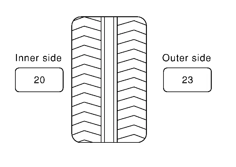
Calculation example:
23 g (0.81 oz) × 5/3 = 38.33 g (1.35 oz) ⇒ 40 g (1.41 oz) balance weight (closer to calculated balance weight value)
NOTE:
Note that balance weight value must be closer to the calculated balance weight value.
Example:
37.4 ⇒ 35 g (1.23 oz)
37.5 ⇒ 40 g (1.41 oz)
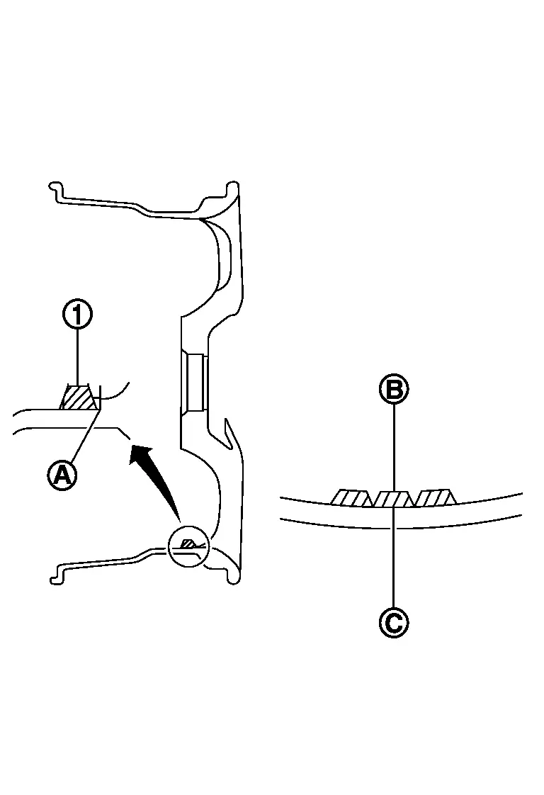
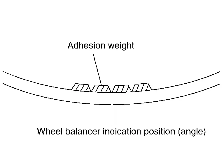
Installed balance weight in the position.-
When installing balance weight
to road wheels, set it into the grooved area on the inner wall of the road wheel as shown in the figure so that the balance weight center  is aligned with the tire balance machine indication position (angle)
  .
.
CAUTION:
-
Always use genuine NISSAN balance weights.
-
Balance weights are non-reusable; always replace with new ones.
-
Never install three or more sheets of balance weight.
-
CAUTION:
Never install one balance weight sheet on top of another.
Start the tire balance machine again.
Install drive-in balance weight on inner side of road wheel in the tire balance machine indication position (angle).
CAUTION:
Never install three or more balance weight.
Start the tire balance machine. Check that the inner and outer residual unbalance value is within the allowable unbalance value.
CAUTION:
If either residual unbalance value exceeds limit, repeat installation procedures.
| Allowable unbalance value | |
| Dynamic (At flange) | Refer to Road Wheel. |
| Static (At flange) | Refer to Road Wheel. |
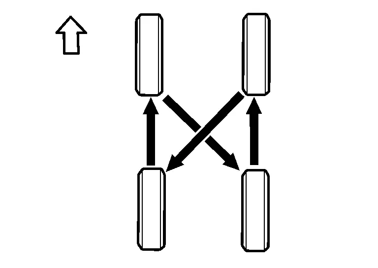
Tire Rotation
-
Follow the maintenance schedule for tire rotation service intervals. Refer to General Maintenance.
-
When installing the wheel, tighten wheel nuts to the specified torque. Refer to Exploded View.
CAUTION:
-
Never include the T-type spare tire when rotating the tires.
-
When installing wheels, tighten them diagonally by dividing the work two to three times in order to prevent the wheels from developing any distortion.
-
Never tighten wheel nut at torque exceeding the criteria.
-
Use NISSAN genuine wheel nut.
-
-
After tire rotation, perform following:
-
Perform the ID registration. Refer to Work Procedure.
-
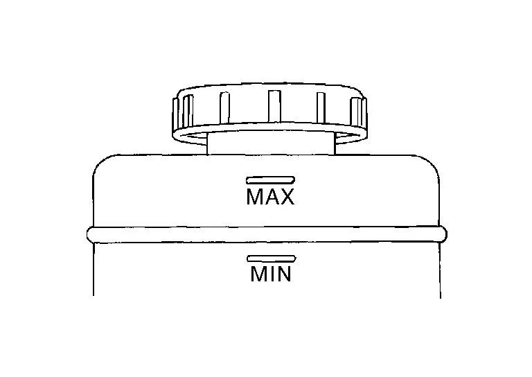
Brake Fluid Level and Leaks
Inspection
-
If fluid level is extremely low, check brake system for leaks.
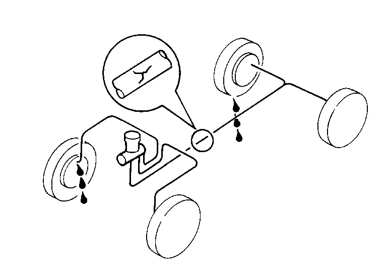
Brake Lines and Cables
Inspection
-
Check brake/clutch fluid lines and parking brake cables for improper attachment, leaks, chafing, abrasions, deterioration, etc.
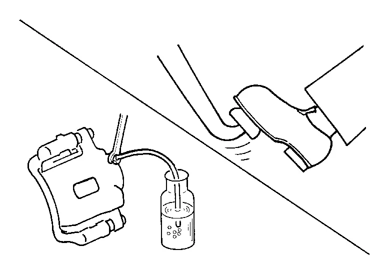
Brake Fluid
Changing
-
Drain brake fluid from each bleed valve.
-
Refill until new brake fluid comes out from each bleed valve.
Use same procedure as in bleeding hydraulic system to refill brake fluid.
Refer to Bleeding Brake System.
-
Refill with recommended brake fluid.
Refer to Fluids and Lubricants.
-
Never reuse drained brake fluid.
-
Be careful not to splash brake fluid on painted areas.
-
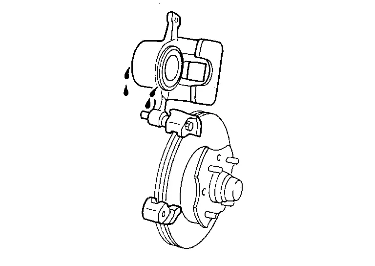
Disk Brake
Inspection
DISC ROTOR
Check condition, wear, and damage.
CALIPER
-
Check for leakage.
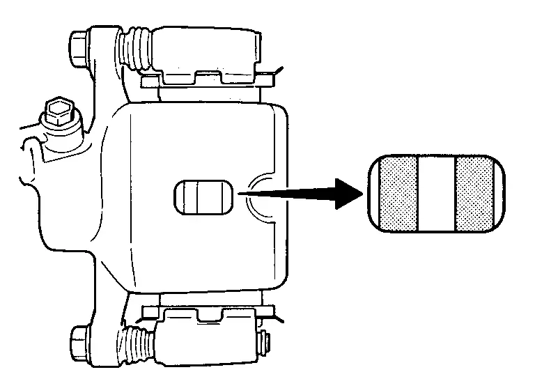
BRAKE PAD
-
Check for wear or damage.
Front Disc Brake
Unit: mm (in)
| Item | Limit | |
|---|---|---|
| Brake pad | Wear thickness | 2.0 (0.079) |
| Disc rotor | Wear thickness | 23.4 (0.921) |
| Thickness variation (measured at 8 positions)* | 0.020 (0.0008) | |
| Runout (with it attached to the Nissan Ariya vehicle) | 0.035 (0.0014) | |
*To check if rotor imbalance, rotor runout or rotor deformation is occured.
Rear Disc Brake
Unit: mm (in)
| Item | Limit | |
|---|---|---|
| Brake pad | Wear thickness | 2.0 (0.079) |
| Disc rotor | Wear thickness | 14.0 (0.551) |
| Thickness variation (measured at 8 positions)* | 0.020 (0.0008) | |
| Runout (with it attached to the Nissan Ariya vehicle) | 0.070 (0.0028) | |
*To check if rotor imbalance, rotor runout or rotor deformation is occured.
Steering Gear and Linkage
Inspection
STEERING GEAR
-
Check gear housing and boots for looseness, damage and grease leakage.
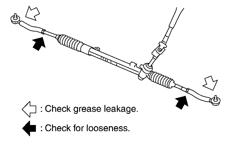
-
Check connection with steering column for looseness.
STEERING LINKAGE
Check ball joint, dust cover and other component parts for looseness, wear, damage and grease leakage.
Axle and Suspension Parts
Inspection
Check front and rear axle and suspension parts for excessive play, cracks, wear or other damage.
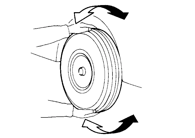
-
Shake each wheel to check for excessive play.
-
Check wheel bearings for smooth operation.
-
Check axle and suspension nuts and bolts for looseness.
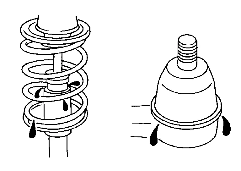
-
Check strut (shock absorber) for oil leakage or other damage.
-
Check suspension ball joint for grease leakage and ball joint dust cover for cracks or other damage.
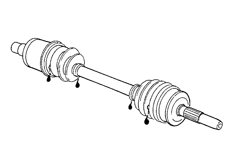
Drive Shaft
Inspection
-
Check boot and drive shaft for cracks, wear, damage and grease leakage.
Other materials:
Preparation
Special Service Tool
The actual shapes of TechMate tools may differ from those of special service tools illustrated here.
Tool number
(TechMate No.)
Tool name Description
(NI-39570)
Chassis ear
Locates the noise
(NI-50397)
Squeak and Rattle Kit
Repairs the ca ...
Front Camera Unit Heater
Component Inspection
CHECK FRONT CAMERA UNIT HEATER
Check the resistance between the front camera unit heater terminals.
Front camera unit heater Resistance [Ω]
Terminal
1
4
7 – 20
Is the inspection result normal?
YES>>
INSPECTION END
NO>>
Replace the fro ...
Symptom Diagnosis. Wiper Deicer Does Not Operate
Diagnosis Procedure
CHECK WIPER DEICER RELAY
Check wiper deicer relay.
Refer to Component Inspection.
Is the inspection result normal?
YES>>
GO TO 2.
NO>>
Repair or replace the malfunctioning parts.
CHECK WIPER DEICER
Check wiper deicer.
Refer to Component Function Check.
I ...