Nissan Rogue (T33) 2021-Present Service Manual: Periodic Maintenance :: Brake Pedal
Inspection and Adjustment
INSPECTION
Brake Pedal Height
Check the height (H1) between the floor panel  and the brake pedal upper surface.
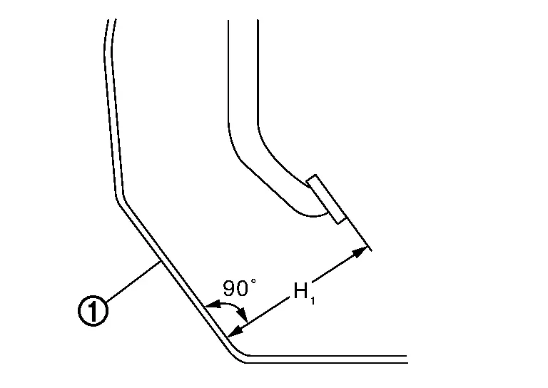
| H1 | : Refer to Brake Pedal. |
CAUTION:
Remove the front floor carpet.
Stop Lamp Switch
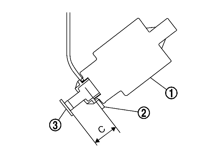
Check the clearance (C) among the lever and the stop lamp switch mounting bracket  .
.
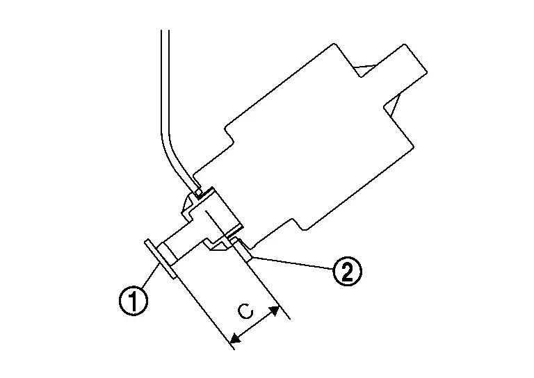
| C | : Refer to Brake Pedal. |
CAUTION:
The stop lamp must turn off when the brake pedal is released.
 NOTE:
NOTE:
Hold the brake pedal pad to make the clearance between the stop lamp switch mounting bracket and brake pedal.
Brake Pedal Play
Press the brake pedal. Check the brake pedal play (A) (stroke until fluid pressure occurs).
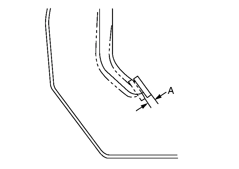
| A | : Refer to Brake Pedal. |
Depressed Brake Pedal Height
Check the height between the floor panel and the brake pedal upper surface (H2) when depressing the brake pedal at 490 N (50 kg, 110 lb) while turning engine ON.
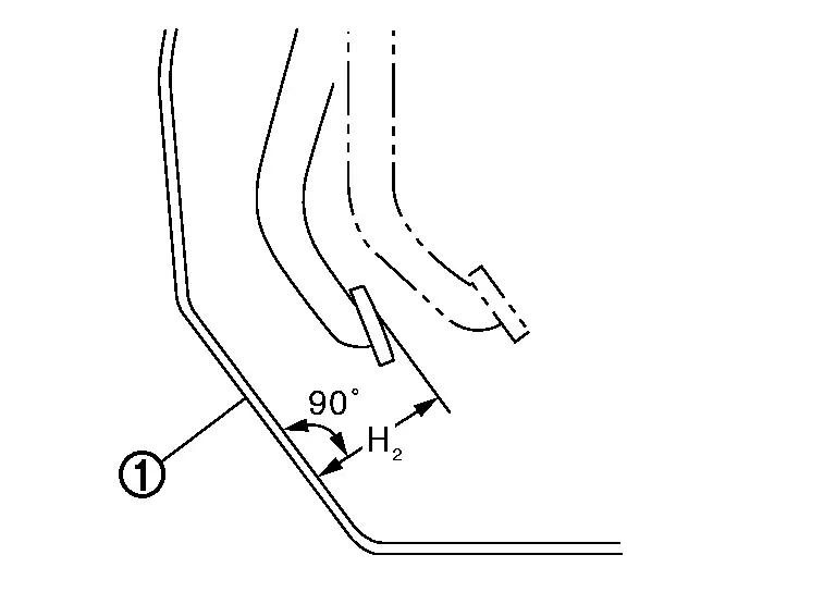
| H2 | : Refer to Brake Pedal. |
CAUTION:
Remove the front floor carpet.
ADJUSTMENT
Brake Pedal Height
Perform the following procedure when brake pedal height is not within the specified value because brake pedal height is not adjustable.
Check the input rod length. Refer to Inspection and Adjustment (without ProPILOT Assist 2.1) or to Electrically-Driven Intelligent Brake Unit (with ProPILOT Assist 2.1).
Replace the brake booster (without ProPILOT Assist 2.1) or the electrically-driven intelligent brake unit (with ProPILOT Assist 2.1) when the input rod length is not the standard.
Stop Lamp Switch
Remove instrument lower panel LH. Refer to Removal and Installation.
Disconnect the harness connector from stop lamp switch.
Loosen the stop lamp switch 90┬░ counterclockwise.
The stop lamp switch penetrate the clip hole of stop lamp switch mounting bracket and firmly push the stop lamp switch against the lever  .
(Do not touch the pedal during installing stop lamp switch.) And, turn
the stop lamp switch clockwise (about 90┬░) until the stop lamp switch.
.
(Do not touch the pedal during installing stop lamp switch.) And, turn
the stop lamp switch clockwise (about 90┬░) until the stop lamp switch.
CAUTION:
-
The clearance (C) between the brake pedal bracket and stop lamp switch mounting bracket must be the specified value.
C : Refer to Brake Pedal. -
The stop lamp must be turned off when the brake pedal is released.
Depressed Brake Pedal Height
Perform the air bleeding. Refer to Bleeding Brake System.
Check the height between the floor panel and the brake pedal upper surface (H2) when depressing the brake pedal at 490 N (50 kg, 110 lb) while turning engine ON.
| H2 | : Refer to Brake Pedal. |
CAUTION:
Remove the front floor carpet.
Other materials:
Component Parts
Propilot Assist 1.1
Component Parts Location
No. Component Function
1.
Front camera unit
Refer to Component Parts Location for detailed component location.
2.
AV control unit
Refer to Component Parts Location for detailed component location.
3.
Chassis control modu ...
System Description. Component Parts. Moonroof System
Moonroof System
Component Description
No. Component Function
1.
Moonroof switch assembly
Refer to Moonroof Switch Assembly.
2.
Moonroof motor assembly
Refer to Moonroof Motor Assembly.
3.
Front door lock assembly RH (door switch)
Detects door open/close condition ...
P2135 Tp Sensor
DTC Description
DTC DETECTION LOGICNOTE:
If DTC P2135 is displayed with DTC P06B0, first perform the trouble diagnosis for DTC P06B0. Refer to DTC Description.
DTC
CONSULT screen terms
(Trouble diagnosis content)
DTC detection condition
P2135
00
TP SENSOR-B1
(Throttle/Pedal ...