Nissan Rogue Service Manual: Parking brake rear cable
Removal and Installation
REMOVAL
- Remove the center console assembly. Refer to IP-18, "Removal and Installation".
- Remove shift selector. Refer to TM-194, "Removal and Installation".
- Remove the bolts from the parking brake front cable mount. Refer to PB-7, "Exploded View".
- Loosen the adjusting nut. Refer to PB-7, "Exploded View".
NOTE: It is not necessary to remove the parking brake front cable.
- Pull equalizer (A) of the parking brake front cable (1) in a
rearward direction and then push upward to separate
each parking brake rear cable (2) from the parking brake front cable (1).
CAUTION: To prevent damage to the parts, do not bend the parking brake cables.
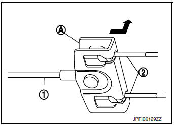
- Press the pawl (1) to remove each parking brake rear cable from the vehicle.
- Remove the parking brake shoes, and separate the parking brake rear cable from the toggle lever. Refer to PB-11, "Removal and Installation".
INSTALLATION
Installation is in the reverse order of removal.
CAUTION: Do not reuse the adjusting nut if the nut is removed.
- Inspect and adjust the parking brake pedal. Refer to PB-4, "Inspection and Adjustment".
- Inspect and adjust the parking brake shoes. Refer to PB-6, "Inspection and Adjustment".
 Parking brake front cable
Removal and Installation
REMOVAL
Remove the instrument lower panel LH. Refer to IP-22, "Removal and
Installation".
Remove driver seat (LH). Refer to SE-32, "DRIVER ...
 Parking brake switch
Removal and Installation
REMOVAL
Remove the instrument lower panel LH. Refer to IP-22, "Removal and
Installation".
Disconnect the harness connector from the parking bra ...
Other materials:
Removal and installation
HORN
Exploded View
Horn (LOW)
Horn (HIGH)
Removal and Installation
REMOVAL
Horn (LOW)
Remove the front grille. Refer to EXT-23, "Removal and
Installation".
Disconnect the harness connectors from the horn (LOW).
NOTE:
Before disconnecting the harn ...
Service data and specifications (SDS)
General Specification
CAUTION:
Use only Genuine NISSAN CVT Fluid NS-3. Never mix with other
fluid.
Using CVT fluid other than Genuine NISSAN CVT Fluid NS-3 will
deteriorate in driveability and CVT durability, and may damage
the CVT, which is not covered by the NISSAN n ...
Unit disassembly and assembly
COMBINATION METER
Exploded View
Combination meter
Combination meter lens
Pawl
Disassembly and Assembly
CAUTION:
Do not touch the display, pointer, inside of combination meter
or the printed area of the dial during
disassembly or assembly.
Keep away from magn ...
