Nissan Rogue Service Manual: P084c transmission fluid pressure SEN/SW H
DTC Description
DTC DETECTION LOGIC
| DTC | CONSULT screen terms (Trouble diagnosis content) | DTC detection condition |
| P084C | FLUID PRESS SEN/SW H (Transmission Fluid Pressure Sensor/Switch H Circuit Low) | When all of the following conditions are satisfied and this state is
maintained
for 5 seconds:
|
POSSIBLE CAUSE
- Harness or connector (Primary pressure sensor circuit is open or shorted to ground)
- Primary pressure sensor
- Control valve assembly
FAIL-SAFE
Not changed from normal driving
DTC CONFIRMATION PROCEDURE
1.PREPARATION BEFORE WORK
If another "DTC CONFIRMATION PROCEDURE" occurs just before, turn ignition switch OFF and wait for at least 10 seconds, then perform the next test.
>> GO TO 2.
2.CHECK DTC DETECTION
With CONSULT
- Start the engine.
- Select ÔÇťData MonitorÔÇŁ in ÔÇťTRANSMISSIONÔÇŁ.
- Select ÔÇťFLUID TEMPÔÇŁ.
- Maintain the following conditions for 10 seconds or more.
FLUID TEMP : More than Ôłĺ20┬░C (Ôłĺ4┬░F)
- Check the first trip DTC.
With GST
- Start the engine and wait for at least 10 seconds.
CAUTION: When the ambient temperature is less than Ôłĺ20┬░C (Ôłĺ4┬░F) and the engine is cold, warm up the engine for approximately 5 minutes.
- Check the first trip DTC.
Is ÔÇťP084CÔÇŁdetected? YES >> Go to TM-150, "Diagnosis Procedure".
NO-1 >> To check malfunction symptom before repair: Refer to GI-41, "Intermittent Incident".
NO-2 >> Confirmation after repair: INSPECTION END
Diagnosis Procedure
1.CHECK TCM INPUT SIGNALS
- Turn ignition switch OFF.
- Start the engine.
- Check voltage between TCM harness connector terminals.
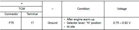
Is the inspection result normal? YES >> INSPECTION END
NO >> GO TO 2.
2.CHECK CIRCUIT BETWEEN TCM AND CVT UNIT (PART 1)
- Turn ignition switch OFF.
- Disconnect TCM connector and CVT unit connector.
- Check continuity between TCM harness connector terminals and CVT unit harness connector terminals.
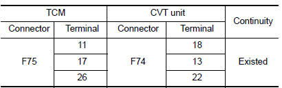
Is the inspection result normal? YES >> GO TO 3.
NO >> Repair or replace malfunctioning parts.
3.CHECK CIRCUIT BETWEEN TCM AND CVT UNIT (PART 2)
Check continuity between TCM harness connector terminals and ground.
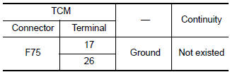
Is the inspection result normal? YES >> There is malfunction of primary pressure sensor. Replace transaxle assembly. Refer to TM-220, "Removal and Installation".
NO >> Repair or replace malfunctioning parts.
 P0848 transmission fluid pressure SEN/SW B
DTC Description
DTC DETECTION LOGIC
DTC
CONSULT screen terms
(Trouble diagnosis content)
DTC detection condition
P0848
FLUID PRESS SEN/SW B
(Transmission Fluid Pressur ...
 P084d transmission fluid pressure SEN/SW H
DTC Description
DTC DETECTION LOGIC
DTC
CONSULT screen terms
(Trouble diagnosis content)
DTC detection condition
P084D
FLUID PRESS SEN/SW H
(Transmission Fluid Pressur ...
Other materials:
P0112, P0113 IAT sensor
DTC Description
DTC DETECTION LOGIC
DTC No.
CONSULT screen terms
(Trouble diagnosis content)
DTC detecting condition
P0112
IAT SEN/CIRCUIT- B1
(Intake air temperature sensor 1 circuit low
bank 1)
An excessively low voltage from the intake air temperature sensor ...
Operating range
Operating range
The Intelligent Key functions can only be used
when the Intelligent Key is within the specified
operating range.
When the Intelligent Key battery is almost discharged
or strong radio waves are present near
the operating location, the Intelligent Key systemÔÇÖs
operating ...
Removal and installation
FRONT AIR CONTROL
Removal and Installation
REMOVAL
Release the front air control clips and pawls using a suitable
tool.
: Metal clip
: Pawl
Disconnect the harness connector from the front air control (1)
and remove.
INSTALLATION
Installation is in the reverse order of ...
