Nissan Rogue Service Manual: Removal and installation
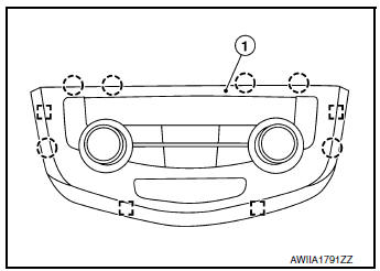
FRONT AIR CONTROL
Removal and Installation
REMOVAL
- Release the front air control clips and pawls using a suitable tool.
 : Metal clip
 : Pawl
- Disconnect the harness connector from the front air control (1) and remove.
INSTALLATION
Installation is in the reverse order of removal.
INTAKE SENSOR
Exploded View
- Intake sensor
- Heating and cooling unit assembly
Removal and Installation
REMOVAL
- Remove front foot duct (LH). Refer to VTL-10, "FRONT FOOT DUCT : Removal and Installation".
- Disconnect the harness connector and remove intake sensor.
INSTALLATION
Installation is in the reverse order of removal.
REFRIGERANT PRESSURE SENSOR
Removal and Installation
REMOVAL
- Discharge the refrigerant. Refer to HA-23, "Recycle Refrigerant".
- Remove front bumper fascia. Refer to EXT-17, "Removal and Installation".
- Disconnect the harness connector from the refrigerant pressure sensor.
- Remove the refrigerant pressure sensor (1) from the condenser.
 : Front
CAUTION: Cap or wrap the opening of the refrigerant pressure sensor with suitable material such as vinyl tape to avoid the entry of air.
INSTALLATION
Installation is in the reverse order of removal.
CAUTION:
- Do not reuse O-ring.
- Apply A/C oil to new O-ring for installation.
- After charging refrigerant, check for leaks. Refer to HA-21, "Leak Test".
DOOR MOTOR
Component Parts Location
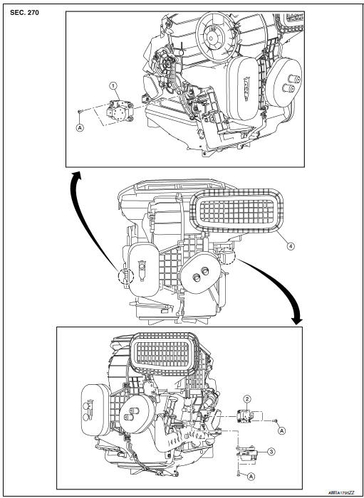
- Mode door motor
- Air mix door motor
- Intake door motor
- Heating and cooling unit assembly
- Screw
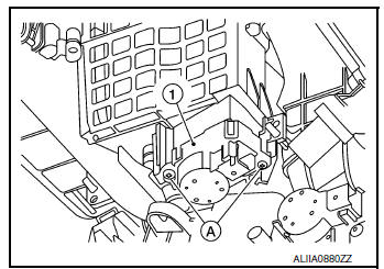
INTAKE DOOR MOTOR
INTAKE DOOR MOTOR : Removal and Installation
REMOVAL
- Remove front foot duct (LH). Refer to VTL-10, "FRONT FOOT DUCT : Removal and Installation".
- Disconnect the harness connector from the intake door motor.
- Remove screws (A) and intake door motor (1).
INSTALLATION
Installation is in the reverse order of removal.
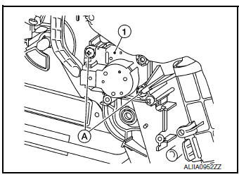
MODE DOOR MOTOR
MODE DOOR MOTOR : Removal and Installation
REMOVAL
- Remove front foot duct (RH). Refer to VTL-10, "FRONT FOOT DUCT : Removal and Installation".
- Disconnect the harness connector from the mode door motor.
- Remove screws (A) and mode door motor (1).
INSTALLATION
Installation is in the reverse order of removal.
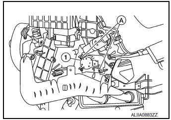
AIR MIX DOOR MOTOR
AIR MIX DOOR MOTOR : Removal and Installation
REMOVAL
- Remove front foot duct (LH). Refer to VTL-10, "FRONT FOOT DUCT : Removal and Installation".
- Disconnect the harness connector from the air mix door motor.
- Remove screws (A) and air mix door motor (1).
INSTALLATION
Installation is in the reverse order of removal.
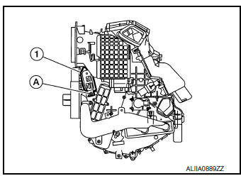
VARIABLE BLOWER CONTROL
Removal and Installation
REMOVAL
- Remove center console side finisher (LH). Refer to IP-18, "Exploded View"
- Disconnect the harness connector from the variable blower control.
- Remove screw (A) and variable blower control (1).
INSTALLATION
Installation is in the reverse order of removal.
 Symptom diagnosis
HEATER AND AIR CONDITIONING SYSTEM CONTROL SYMPTOMS
Symptom Table
SYMPTOM TABLE
Symptom
Reference Page
A/C system does not come on.
Go to Trouble Diagnosis Procedure f ...
 Body interior
...
Other materials:
System description
CAN COMMUNICATION SYSTEM
System Description
CAN communication is a multiplex communication system. This enables the
system to transmit and receive
large quantities of data at high speed by connecting control units with two
communication lines (CAN-H and
CAN-L).
Control units o ...
Precaution
Precaution for Supplemental Restraint System (SRS) "AIR BAG" and "SEAT
BELT
PRE-TENSIONER"
The Supplemental Restraint System such as “AIR BAG” and “SEAT BELT PRE-TENSIONER”,
used along
with a front seat belt, helps to reduce the risk or severity of injury to the
...
Power supply and ground circuit
BCM (BODY CONTROL SYSTEM) (WITH INTELLIGENT KEY SYSTEM)
BCM (BODY CONTROL SYSTEM) (WITH INTELLIGENT KEY SYSTEM) : Diagnosis
Procedure
Regarding Wiring Diagram information, refer to BCS-50, "Wiring Diagram".
1. CHECK FUSE
Check that the following fuse is not blown.
Is the fuse blo ...
