Nissan Rogue Service Manual: P0848 transmission fluid pressure SEN/SW B
DTC Description
DTC DETECTION LOGIC
| DTC | CONSULT screen terms (Trouble diagnosis content) | DTC detection condition |
| P0848 | FLUID PRESS SEN/SW B (Transmission Fluid Pressure Sensor/Switch B Circuit Low) | When all of the following conditions are satisfied and this state is
maintained
for 5 seconds:
|
POSSIBLE CAUSE
- Harness or connector (Secondary pressure sensor circuit is shorted to power supply)
- Secondary pressure sensor
- Control valve assembly
FAIL-SAFE
Not changed from normal driving
DTC CONFIRMATION PROCEDURE
1.PREPARATION BEFORE WORK
If another "DTC CONFIRMATION PROCEDURE" occurs just before, the ignition switch OFF and wait for at least 10 seconds, then perform the next test.
>> GO TO 2.
2.CHECK DTC DETECTION
 With CONSULT
- Start the engine.
- Select ÔÇťData MonitorÔÇŁ in ÔÇťTRANSMISSIONÔÇŁ.
- Select ÔÇťFLUID TEMPÔÇŁ.
- Maintain the following conditions for 10 seconds or more.
FLUID TEMP : More than Ôłĺ20┬░C (Ôłĺ4┬░F)
- Check the first trip DTC.
 With GST
- Start the engine and wait for at least 10 seconds.
CAUTION: When the ambient temperature is less than Ôłĺ20┬░C (Ôłĺ4┬░F) and the engine is cold, warm up the engine for approximately 5 minutes.
- Check the first trip DTC.
Is ÔÇťP0848ÔÇŁdetected? YES >> Go to TM-148, "Diagnosis Procedure".
NO-1 >> To check malfunction symptom before repair: Refer to GI-41, "Intermittent Incident".
NO-2 >> Confirmation after repair: INSPECTION END
Diagnosis Procedure
1.CHECK TCM INPUT SIGNALS
- Turn ignition switch OFF.
- Start the engine.
- Check voltage between TCM harness connector terminals.
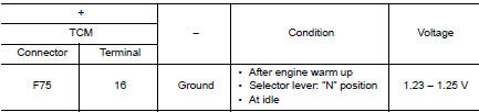
Is the inspection result normal? YES >> INSPECTION END
NO >> GO TO 2.
2.CHECK SECONDARY PRESSURE SENSOR POWER CIRCUIT
- Turn ignition switch OFF.
- Connect TCM connector.
- Disconnect CVT unit connector.
- Check voltage between CVT unit harness connector terminal and ground.
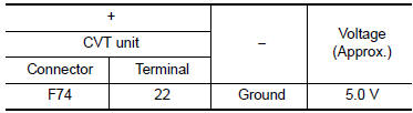
Is the inspection result normal? YES >> GO TO 3.
NO >> Repair or replace malfunctioning parts.
3.CHECK SECONDARY PRESSURE SENSOR SIGNAL CIRCUIT
eck voltage between CVT unit harness connector terminal and ground.
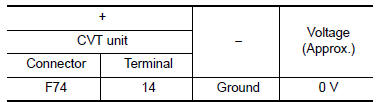
Is the inspection result normal? YES >> There is malfunction of secondary pressure sensor. Replace transaxle assembly. Refer to TM- 220, "Removal and Installation".
NO >> Repair or replace malfunctioning parts.
 P0847 transmission fluid pressure SEN/SW B
DTC Description
DTC DETECTION LOGIC
DTC
CONSULT screen terms
(Trouble diagnosis content)
DTC detection condition
P0847
FLUID PRESS SEN/SW B
(Transmission Fluid Pressur ...
 P084c transmission fluid pressure SEN/SW H
DTC Description
DTC DETECTION LOGIC
DTC
CONSULT screen terms
(Trouble diagnosis content)
DTC detection condition
P084C
FLUID PRESS SEN/SW H
(Transmission Fluid Pressur ...
Other materials:
Preparation
Special Service Tool
Tool number
(TechMate No.)
Tool name
Description
ÔÇö
(J-46534)
Trim Tool Set
Removing trim components
Commercial Service Tool
(TechMate No.)
Tool name
Description
( ÔÇö )
Power tool
Loo ...
Squeak and rattle trouble diagnoses
Work Flow
CUSTOMER INTERVIEW
Interview the customer if possible, to determine the conditions that exist
when the noise occurs. Use the Diagnostic
Worksheet during the interview to document the facts and conditions when the
noise occurs and any
customer's comments; refer to RF-47, &qu ...
Diagnosis system (BCM) (without intelligent key system)
COMMON ITEM
COMMON ITEM : CONSULT Function (BCM - COMMON ITEM)
APPLICATION ITEM
CONSULT performs the following functions via CAN communication with BCM.
SYSTEM APPLICATION
BCM can perform the following functions.
BUZZER
BUZZER : CONSULT Function (BCM - BUZZER)
DATA MONITOR
ACTIV ...
