Nissan Rogue Service Manual: P0847 transmission fluid pressure SEN/SW B
DTC Description
DTC DETECTION LOGIC
| DTC | CONSULT screen terms (Trouble diagnosis content) | DTC detection condition |
| P0847 | FLUID PRESS SEN/SW B (Transmission Fluid Pressure Sensor/Switch B Circuit Low) | When all of the following conditions are satisfied and this state is
maintained
for 5 seconds:
|
POSSIBLE CAUSE
- Harness or connector (Secondary pressure sensor circuit is open or shorted to ground)
- Secondary pressure sensor
- Control valve assembly
FAIL-SAFE
Not changed from normal driving
DTC CONFIRMATION PROCEDURE
1.PREPARATION BEFORE WORK
If another "DTC CONFIRMATION PROCEDURE" occurs just before, turn ignition switch OFF and wait for at least 10 seconds, then perform the next test.
>> GO TO 2.
2.CHECK DTC DETECTION
 With CONSULT
- Start the engine.
- Select ÔÇťData MonitorÔÇŁ in ÔÇťTRANSMISSIONÔÇŁ.
- Select ÔÇťFLUID TEMPÔÇŁ.
- Maintain the following conditions for 10 seconds or more.
FLUID TEMP : Ôłĺ20┬░C (Ôłĺ4┬░F)
- Check the first trip DTC.
 With GST
- Start the engine and wait for at least 10 seconds.
CAUTION: When the ambient temperature is less than Ôłĺ20┬░C (Ôłĺ4┬░F) and the engine is cold, warm up the engine for approximately 5 minutes.
- Check the first trip DTC.
Is ÔÇťP0847ÔÇŁdetected? YES >> Go to TM-146, "Diagnosis Procedure".
NO-1 >> To check malfunction symptom before repair: Refer to GI-41, "Intermittent Incident".
NO-2 >> Confirmation after repair: INSPECTION END
Diagnosis Procedure
1.CHECK TCM INPUT SIGNALS
- Turn ignition switch OFF.
- Start the engine.
- Check voltage between TCM harness connector terminals.
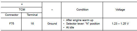
Is the inspection result normal? YES >> INSPECTION END
NO >> GO TO 2.
2.CHECK CIRCUIT BETWEEN TCM AND CVT UNIT (PART 1)
- Turn ignition switch OFF.
- Disconnect TCM connector and CVT unit connector.
- Check continuity between TCM harness connector terminals and CVT unit harness connector terminals.
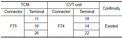
Is the inspection result normal? YES >> GO TO 3.
NO >> Repair or replace malfunctioning parts.
3.CHECK CIRCUIT BETWEEN TCM AND CVT UNIT (PART 2)
Check continuity between TCM harness connector terminals and ground.
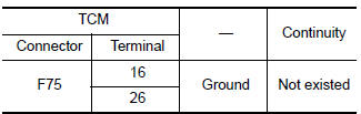
Is the inspection result normal? YES >> There is malfunction of secondary pressure sensor. Replace transaxle assembly. Refer to TM- 220, "Removal and Installation".
NO >> Repair or replace malfunctioning parts.
 P0841 transmission fluid pressure SEN/SW A
DTC Description
DTC DETECTION LOGIC
DTC
CONSULT screen terms
(Trouble diagnosis content)
DTC detection condition
P0841
FLUID PRESS SEN/SW A
(Transmission Fluid Pressur ...
 P0848 transmission fluid pressure SEN/SW B
DTC Description
DTC DETECTION LOGIC
DTC
CONSULT screen terms
(Trouble diagnosis content)
DTC detection condition
P0848
FLUID PRESS SEN/SW B
(Transmission Fluid Pressur ...
Other materials:
C1101, C1102, C1103, C1104 wheel sensor
DTC Logic
DTC DETECTION LOGIC
DTC
Display Item
Malfunction detected condition
Possible causes
C1101
RR RH SENSOR-1
When power supply voltage of rear wheel sensor
RH is low.
When an open or shorted circuit is detected in rear
wheel sensor RH ...
Service data and specifications (SDS)
Wheel Alignment (Unladen*1)
*1: Fuel, engine coolant, and lubricants are full. Spare tire, jack, hand
tools, and mats are in designated positions.
Ball Joint
Wheelarch Height (Unladen*)
*: Fuel, engine coolant, and lubricants are full. Spare tire, jack, hand
tools, and mats are i ...
System description
COMPONENT PARTS
Component Parts Location
View under rear of front passenger
seat
View with spare tire cover removed
Center of back door
View with glove box removed
No.
Component
Function
1
Rod antenna
Refer to AV-232, &quo ...
