Nissan Rogue Service Manual: System description
COMPONENT PARTS
Component Parts Location
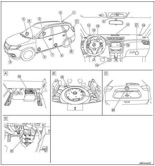
- View under rear of front passenger seat
- View with spare tire cover removed
- Center of back door
- View with glove box removed
|
No. |
Component |
Function |
| 1 | Rod antenna | Refer to AV-232, "Rod Antenna, Antenna Amp., Satellite Antenna and Antenna Feeder". |
| 2 | Antenna base (antenna amp. and satellite antenna) | |
| 3 | Rear door speaker RH | Refer to AV-229, "Speakers". |
| 4 | Front door speaker RH | |
| 5 | Front camera | Refer to AV-231, "Front Camera". |
| 6 | Front door speaker LH | Refer to AV-229, "Speakers". |
| 7 | Side camera | Refer to AV-231, "Side Cameras". |
| 8 | Rear door speaker LH | Refer to AV-229, "Speakers". |
| 9 | Microphone | Refer to AV-230, "Microphone". |
| 10 | GPS antenna | Refer to AV-233, "GPS Antenna". |
| 11 | Front tweeter LH | Refer to AV-229, "Speakers". |
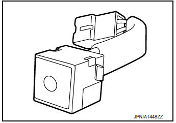
| 12 | Steering angle sensor | Refer to AV-232, "Steering Angle Sensor". |
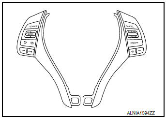
| 13 | Steering switches | Refer to AV-230, "Steering Switches". |
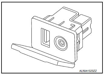
| 14 | USB interface and AUX in jack | Refer to AV-230, "USB Interface and AUX In Jack". |
| 15 | AV control unit | Refer to AV-228, "AV Control Unit". |
| 16 | Front tweeter RH | Refer to AV-229, "Speakers". |
| 17 | Center speaker | Refer to AV-229, "Speakers". |
| 18 | BOSE speaker amp. | Refer to AV-228, "BOSE Speaker Amp.". |
| 19 | Subwoofer | Refer to AV-229, "Speakers". |
| 20 | Rear view camera | Refer to AV-231, "Rear View Camera". |
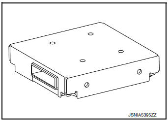
| 21 | Around View®* Monitor control unit | Refer to AV-231, "Around View Monitor Control Unit". |
*: Around View Monitor is a parking aid/convenience feature. Around View Monitor cannot completely eliminate blind spots. Around View Monitor may not detect every object and does not warn of moving objects. Always check surroundings before moving vehicle. Around View Monitor is not a substitute for proper backing procedures.
Always turn to check what is behind you before backing up.
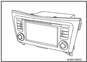
AV Control Unit
Description
- A 7-inch WVGA display, an AM/FM electronic tuner radio, CD drive and navigation unit are integrated into the AV control unit.
- The 7-inch display is a high resolution monitor that includes touch panel functions.
- Music files stored in iPod®*/USB memory can be played using the separate USB interface.
- Music files stored in an external audio device can be played using the separate AUX in jack.
- : iPod® is a registered trademark of Apple, Inc. All rights reserved.
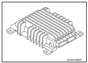
BOSE Speaker Amp.
- Installed under the rear of the front passenger seat.
- Receives sound signal from AV control unit, and outputs sound signal to each tweeter, speaker and the subwoofer.
Speakers
FRONT TWEETER
- 2.5 cm (1 in) tweeters are installed in the top front corners of the instrument panel.
- Sound signals are input from the Bose speaker amp. to output high range sounds.
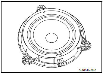
CENTER SPEAKER
- 7.6 cm (3 in) speaker is installed in the top center of the instrument panel.
- Sound signals are input from the Bose speaker amp. to output mid range sounds.
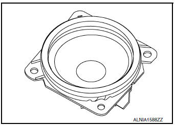
FRONT DOOR SPEAKER
- 16.5 cm (6.5 in) speakers are installed in the bottom of the front doors.
- Sound signals are input from the Bose speaker amp. to output high, mid and low range sounds.
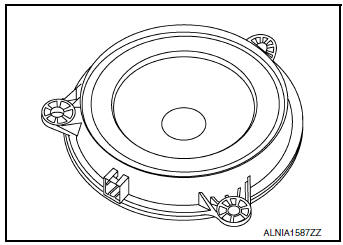
REAR DOOR SPEAKER
- 12.7 cm (5 in) speakers are installed in the bottom of the rear doors.
- Sound signals are input from the Bose speaker amp. to output high, mid and low range sounds.
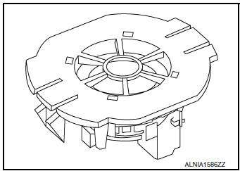
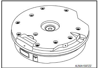
SUBWOOFER
- Installed on top of the spare tire underneath the spare tire cover.
- Sound signals are input from the Bose speaker amp. to output low range sounds.
USB Interface and AUX In Jack
- USB Interface and AUX in jack is installed in the console.
- iPod® and USB memory can be connected to the AV control unit through the USB interface.
- An external audio device can be connected to the AV control unit through the AUX in jack.
Steering Switches
- Steering switches are installed in the steering wheel.
- Operations for audio and hands-free phone are possible.
- Switches are connected to the combination meter.
- Combination meter is connected to the AV control unit via AV communication.
Microphone
- The microphone is installed in the map lamp assembly.
- Power is supplied from the AV control unit.
Around View Monitor Control Unit
- The around view monitor control unit is installed behind the glove box.
- Vehicle width guide lines, predicted course line, vehicle front guiding line and vehicle side line, and vehicle icon are displayed and combined with camera images.
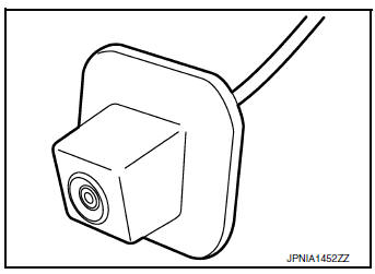
Rear View Camera
- The rear view camera is installed in the back door finisher.
- Power is supplied from the around view monitor control unit.
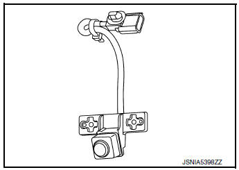
Side Cameras
- The side cameras are installed in the door mirrors.
- Power is supplied from the around view monitor control unit.
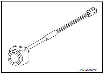
Front Camera
- The front camera is installed in the front grille.
- Power is supplied from the around view monitor control unit.
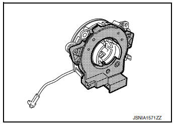
Steering Angle Sensor
- Steering sensor is installed to the spiral cable.
- Steering angle sends the steering signal necessary for predictive course line via CAN communication.
Rod Antenna, Antenna Amp., Satellite Antenna and Antenna Feeder
RADIO ANTENNA AND SATELLITE ANTENNA
AM/FM radio rod antenna, antenna base and satellite antenna are located on the rear of the roof. The antenna amp. and satellite antenna are built into the antenna base.
ANTENNA FEEDER LAYOUT
- Antenna base (antenna amp. and satellite antenna)
- Rod Antenna
- M503
- M502
- M130, M501
- M129, M500
- M142
- M139
GPS Antenna
- GPS antenna is installed in the instrument panel, behind the combination meter.
- Power is supplied from the AV control unit.
SD Card
- Map data is memorized in the SD card.
- Map data is sent to the AV control unit from the SD slot.
SYSTEM
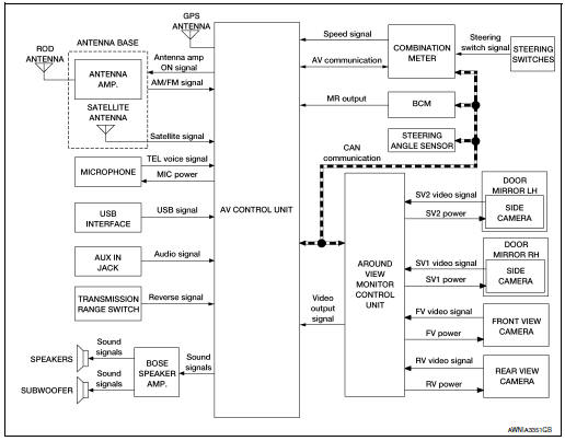
System Description
SYSTEM DIAGRAM
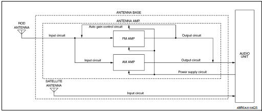
AUDIO SYSTEM
The audio system consists of the following component:
- AV control unit
- Bose speaker amp.
- Front tweeters
- Center speaker
- Front door speakers
- Rear door speakers
- Subwoofer
- USB interface
- AUX in jack
- Antenna base (rod antenna, antenna amp. and satellite antenna)
When the audio system is on, AM/FM signals received by the rod antenna are amplified by the antenna amp.
and sent to the AV control unit. The AV control unit sends the audio signals to the Bose speaker amp. The Bose speaker amp. then sends the audio signals to the tweeters, speakers and subwoofer.
Refer to Owner's Manual for audio system operating instructions.
NAVIGATION SYSTEM
Description
- The navigation system can be operated by control panel of the AV control unit and display (touch panel) of the AV control unit.
- Guide sound during the operation of the navigation system is output from AV control unit to front tweeters.
- AV control unit calculates the vehicle location based on the signals from GYRO (angle speed sensor), vehicle sensor, and GPS satellite, as well as the map data from map SD-card. The vehicle location is displayed on the AV control unit.
POSITION DETECTION PRINCIPLE
The navigation system periodically calculates the vehicle's current position according to the following three signals:
- Travel distance of the vehicle as determined by the vehicle speed sensor
- Turning angle of the vehicle as determined by the gyroscope (angular velocity sensor)
- Direction of vehicle travel as determined by the GPS antenna (GPS information)
The current position of the vehicle is then identified by comparing the calculated vehicle position with map data read from the map SD-card (map-matching), and indicated on the screen as a vehicle mark. More accurate data is judged and used by comparing vehicle position detection results found by the GPS with the result by map-matching.
The current vehicle position will be calculated by detecting the distance the vehicle moved from the previous calculation point and its direction.
- Travel distance
Travel distance calculations are based on the vehicle speed sensor input signal. Therefore, the calculation may become incorrect as the tires wear down. To prevent this, an automatic distance correction function has been adopted. - Travel direction
Change in the travel direction of the vehicle is calculated by a gyroscope (angular velocity sensor) and a GPS antenna (GPS information).They have both advantages and disadvantages.
|
Type |
Advantage |
Disadvantage |
| Gyroscope (angular velocity sensor) | Can detect the vehicle's turning angle quite accurately. | Direction errors may accumulate when vehicle is driven for long distances without stopping. |
| GPS antenna (GPS information) | Can detect the vehicle's travel direction (North/South/East/West). | Correct direction cannot be detected when vehicle speed is low. |
More accurate traveling direction is detected because priorities are set for the signals from these two devices according to the situation.
М
Map-matching compares a current location detected by the method in the “Location Detection Principle” with a road map data from map SD-card.
NOTE: The road map data is based on data stored in the map SD-card.
The vehicle position may not be corrected under the following circumstances and after driving for a certain time when GPS information is difficult to receive. In this case, the vehicle mark on the display must be corrected manually.
- In map-matching, alternative routes to reach the destination will
be
shown and prioritized, after the road on which the vehicle is currently
driven has been judged and the vehicle mark has been repositioned.
Alternative routes will be shown in different order of priority, and the incorrect road can be avoided if there is an error in distance and/or direction.
Routes are of the same priority if two roads are running in parallel.
Therefore, the vehicle mark may appear on either of them alternately, depending on maneuvering of the steering wheel and configuration of the road.
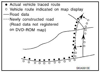
- Map-matching does not function correctly when a road on which
the vehicle is driving is new and not recorded in the map SD-card,
or when road pattern stored in the map data and the actual road
pattern are different due to repair.
The map-matching function may find another road and position the vehicle mark on it when driving on a road not present in the map.
Then, the vehicle mark may change to it when the correct road is detected.
- Effective range for comparing the vehicle position and travel direction calculated by the distance and direction with the road data read from the map SD-card is limited. Therefore, correction by map-matching is not possible when there is an excessive gap between current vehicle position and the position on the map.
GPS (Global Positioning System)
GPS (Global Positioning System) is developed for and is controlled by the US Department of Defense. The system utilizes GPS satellites (NAVSTAR), transmitting out radio waves while flying on an orbit around the earth at an altitude of approximately 21,000 km (13,049 mile).
The receiver calculates the travel position in three dimensions (latitude/ longitude/altitude) according to the time lag of the radio waves that four or more GPS satellites transmit (three-dimensional positioning).
The GPS receiver calculates the travel position in two dimensions (latitude/longitude) with the previous altitude data if the GPS receiver receives only three radio waves (two-dimensional positioning).
GPS position correction is not performed while stopping the vehicle.
Accuracy of the GPS will deteriorate under the following conditions:
- In two-dimensional positioning, GPS accuracy will deteriorate when altitude of the vehicle position changes.
- The position of GPS satellite affects GPS detection precision. The position detection may not be precisely performed.
- The position detection is not performed if GPS receiver does not
receive radio waves from GPS satellites.
(Inside a tunnel, parking in a building, under an elevated highway etc.) GPS receiver may not receive radio waves from GPS satellites if any object is placed on the GPS antenna.
NOTE:
- The detection result has an error of approximately 10 m (32.81 ft) even with a high-precision three dimensional positioning.
- There may be cases when the accuracy is lowered and radio waves are stopped intentionally because the GPS satellite signal is controlled by the US trace control center.
USB INTERFACE
- iPod® or music files in USB memory can be played.
- Sound signals are transmitted from USB interface to the AV control unit and output to each speaker.
- iPod® is recharged when connected to USB interface.
AUX IN JACK
- Sound can be output from an external device by connecting a device to the AUX in jack.
- AUX sound signals are transmitted to each speaker via AV control unit.
SPEED SENSITIVE VOLUME SYSTEM
- Volume level of this system goes up and down automatically in proportion to the vehicle speed.
- The control level can be selected by the customer.
HANDS-FREE PHONE SYSTEM
- Bluetooth® control is built into AV control unit.
- The connection between cellular phone and AV control unit is performed with Bluetooth® communication.
- The voice guidance signal is input from the AV control unit and output to the front speakers when operating the cellular phone.
When A Call Is Originated
- Spoken voice sound output from the microphone (microphone signal) is input to AV control unit.
- AV control unit outputs to cellular phone with Bluetooth® communication as a TEL voice signal.
- Voice sound is then heard at the other party.
When Receiving A Call
- Voice sound is input to own cellular phone from the other party.
- TEL voice signal is input to AV control unit by establishing Bluetooth® communication from cellular phone, and the signal is output to front speakers.
AROUND VIEW MONITOR FUNCTION
- This system is equipped with wide-angle cameras on the front, rear and right and left door mirrors.
- Images from front view, rear view, front-side view (RH side), and birds-eye view are displayed to monitor the vehicle surroundings.
- Around view monitor control unit expands the image received from each camera to create each view.
- In front view and rear view, the vehicle width, distance lines and predictive course lines are displayed.
- In front-side view, the vehicle distance guiding line and vehicle width guiding line are displayed.
- Birds-eye view converts the images from the cameras into an overhead view and displays the status of the vehicle on the display. The vehicle icon that is displayed in the birds-eye view is depicted by the around view monitor control unit.
Display
The around view monitor combines and displays travel direction view (front or rear), front-side view and birdseye view.
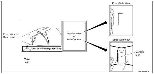
Operation
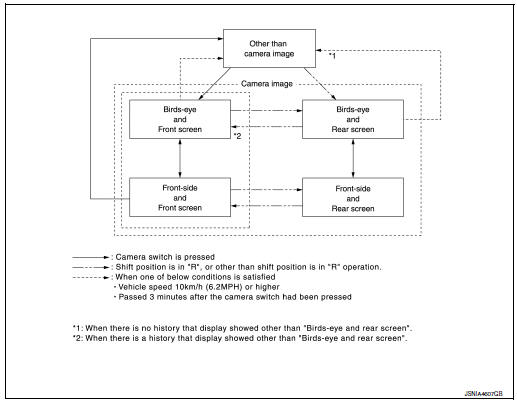
- The around view monitor operates by pressing the CAMERA switch on the AV control unit or by shifting the selector lever to the R (reverse) position.
- When the selector lever is in any position other than R (reverse) and the CAMERA switch is pressed, the screen displays front travel direction view and birds-eye view. Pressing the CAMERA switch again changes birds-eye view to front-side view
- When the selector lever is placed in R (reverse), the screen displays rear travel direction view and birds-eye view. Pressing the CAMERA switch changes birds-eye view to front-side view
- In birds-eye view, the blind spot area is displayed in black to show the border of the camera images. In addition, red fixed lines are displayed in the 4 corners of the vehicle icon. After pressing the CAMERA switch for the first time or placing the selector lever in R (reverse) for the first time, the blind spot area is highlighted in yellow for 3 seconds and the red fixed lines blink five times.
- With the selector lever in any position other than R (reverse), the around view monitor screen display is cancelled 3 minutes after pressing the CAMERA switch. The screen returns to the AV control unit display.
- With the selector lever in R (reverse) position, the around view
monitor screen display remains on constantly.
To return to the AV control unit display, place the selector lever is in any position other than R (reverse).
- If camera image calibration is incomplete, the applicable camera
position is indicated as an error on the
birds-eye view display.
NOTE: Calibration is necessary when replacing each camera or when replacing around view monitor control unit.
Around view monitor screen transition
Front View
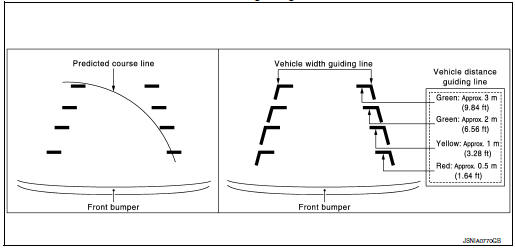
- The front view image improves the visibility of obstacles in front of the vehicle and assists driving by displaying images from birds-eye view and front-side view.
- The front view image displays the vehicle width guiding line and vehicle distance guiding line, in addition to the predictive course line according to the steering angle.
- If the steering angle is within approximately 90 degrees, the predictive course lines on the left/right side are displayed. If the steering angle exceeds approximately 90 degrees, only the predictive course line on the outside is displayed (opposite side of steering direction).
- The around view monitor control unit receives the steering angle signal from steering angle sensor via CAN communication, and controls the direction and distance of the predictive course line.
- ON/OFF setting of predictive course line can be performed using CONSULT.
Front view guiding lines
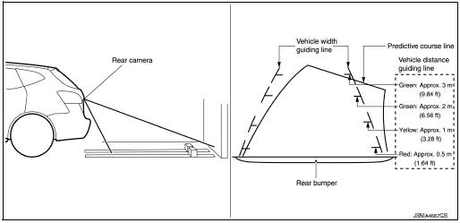
Rear View
- The rear view image improves the visibility of obstacles in the rear of the vehicle and assists backing and parking by displaying images from birds-eye view and front side view.
- The rear view image displays the vehicle width guiding line and vehicle
distance guiding line, in addition to
the predictive course line according to the steering angle.
NOTE: The predictive course line is not displayed at the steering neutral position.
- The around view monitor control unit receives the steering angle signal from steering angle sensor via CAN communication, and controls the direction and distance of the predictive course line.
- ON/OFF setting of predictive course line can be performed using CONSULT.
Rear view guiding lines
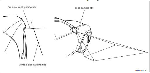
Front-Side View
- The front-side view image improves the visibility of obstacles in the front RH side of the vehicle and assists backing and parking.
- The front-side view image displays the vehicle distance guiding line and vehicle width guiding line.
Front-side view area and guiding line
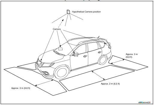
Birds-Eye View
- The birds-eye view image improves the visibility of obstacles all around the vehicle and assists backing and parking.
- The images from the four cameras are converted into an overhead view, and the surroundings of the vehicle are displayed.
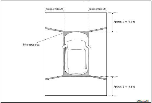
- The blind spot area is displayed on the image to specify the boundary of the four cameras.
Birds-Eye view display image
Birds-Eye view display area
DIAGNOSIS SYSTEM (AV CONTROL UNIT)
Description
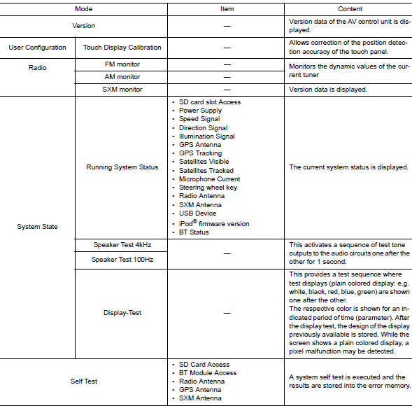
The AV control unit on board diagnosis performs the functions listed in the table below:
Perform CONSULT diagnosis if the AV control unit on board diagnosis does not start or the screen does not display anything.
On Board Diagnosis Function
METHOD OF STARTING
- Turn the ignition ON.
- While pressing the APPS button, turn the TUNE-SCROLL dial counterclockwise 3 or more clicks, then clockwise 3 or more clicks, then counterclockwise 3 or more clicks. Shifting from current screen to previous screen is performed by pressing BACK button.
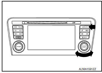
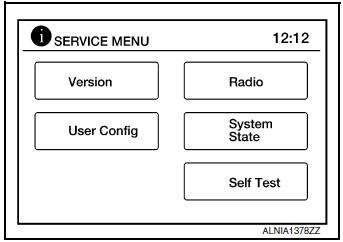
- The trouble diagnosis initial screen is displayed, and Version, User Config, Radio, System State or Self Test can be selected.
CONSULT Function
CONSULT FUNCTIONS
CONSULT performs the following functions via communication with the AV control unit.
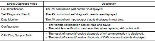
ECU IDENTIFICATION
The part number of AV control unit is displayed.
SELF DIAGNOSTIC RESULT
Refer to AV-251, "DTC Index".
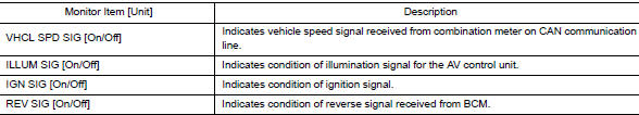
DATA MONITOR
CONFIGURATION
Refer to AV-289, "CONFIGURATION (AV CONTROL UNIT) : Description".
CAN DIAG SUPPORT MNTR
Refer to LAN-14, "CAN Diagnostic Support Monitor".
DIAGNOSIS SYSTEM (AROUND VIEW MONITOR CONTROL UNIT)
WITHOUT DRIVER ASSISTANCE SYSTEM
WITHOUT DRIVER ASSISTANCE SYSTEM : CONSULT Function
CONSULT FUNCTIONS
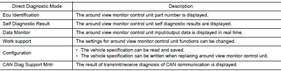
CONSULT performs the following functions via communication with the around view monitor control unit.
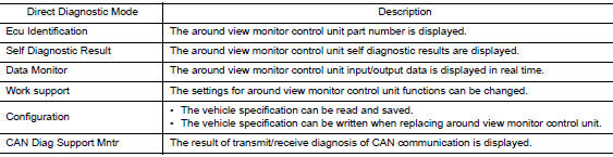
ECU IDENTIFICATION
The part number of around view monitor control unit is displayed.
SELF DIAGNOSTIC RESULT
Refer to AV-257, "WITHOUT DRIVER ASSISTANCE SYSTEM : DTC Index".
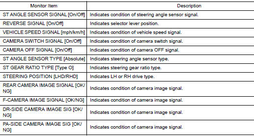
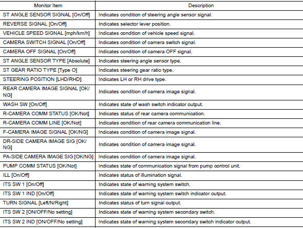
DATA MONITOR
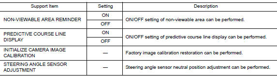
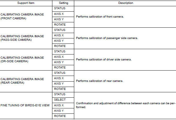
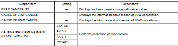
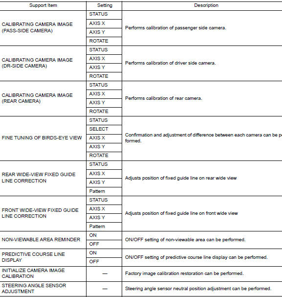
WORK SUPPORT
CONFIGURATION
Refer to AV-290, "CONFIGURATION (AROUND VIEW MONITOR CONTROL UNIT) : Description".
CAN DIAG SUPPORT MNTR
Refer to LAN-14, "CAN Diagnostic Support Monitor".
WITH DRIVER ASSISTANCE SYSTEM
WITH DRIVER ASSISTANCE SYSTEM : CONSULT Function
CONSULT FUNCTIONS
CONSULT performs the following functions via communication with the around view monitor control unit.
ECU IDENTIFICATION
The part number of around view monitor control unit is displayed.
SELF DIAGNOSTIC RESULT
Refer to AV-261, "WITH DRIVER ASSISTANCE SYSTEM : DTC Index".
DATA MONITOR
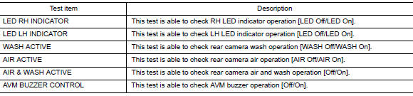
ACTIVE TEST
WORK SUPPORT
CONFIGURATION
Refer to AV-289, "CONFIGURATION (AV CONTROL UNIT) : Description".
CAN DIAG SUPPORT MNTR
Refer to LAN-14, "CAN Diagnostic Support Monitor".
 Preparation
Special Service Tool
The actual shape of the tools may differ from those illustrated here
Tool number
(TechMate No.)
Tool name
Description
—
(J-46534)
Trim T ...
 ECU diagnosis information
AV CONTROL UNIT
Reference Value
VALUES ON THE DIAGNOSIS TOOL
TERMINAL LAYOUT
PHYSICAL VALUES
DTC Index
BOSE SPEAKER AMP
Reference Value
TERMINAL LAYOUT
PHYSICAL ...
Other materials:
Periodic maintenance
IN-CABIN MICROFILTER
Removal and Installation
REMOVAL
Release the tab and remove the in-cabin microfilter cover (1)
from under the RH side of the instrument panel.
CAUTION:
Use care when lifting up on the tab to avoid damaging it.
Remove the in-cabin microfilter (2).
CAUT ...
Preparation
Special Service Tool
Tool number
(TechMate No.)
Tool name
Description
—
(J-46534)
Trim Tool Set
Removing trim components
Commercial Service Tool
(TechMate No.)
Tool name
Description
( — )
Power tool
Loo ...
C1716, C1717, C1718, C1719 transmitter (pressure data)
DTC Logic
NOTE:
The Signal Tech II Tool [- (J-50190)] can be used to perform the following
functions. Refer to the Signal Tech II
User Guide for additional information.
Activate and display TPMS sensor IDs
Display tire pressure reported by the TPMS sensor
Read TPMS DTC ...
