Nissan Rogue Service Manual: P084d transmission fluid pressure SEN/SW H
DTC Description
DTC DETECTION LOGIC
| DTC | CONSULT screen terms (Trouble diagnosis content) | DTC detection condition |
| P084D | FLUID PRESS SEN/SW H (Transmission Fluid Pressure Sensor/Switch ÔÇťHÔÇŁ Circuit High) | When all of the following conditions are satisfied and this state is
maintained
for 5 seconds:
|
POSSIBLE CAUSE
- Harness or connector (Primary pressure sensor circuit is open or shorted to ground)
- Primary pressure sensor
- Control valve assembly
FAIL-SAFE
Not changed from normal driving
DTC CONFIRMATION PROCEDURE
1.PREPARATION BEFORE WORK
If another "DTC CONFIRMATION PROCEDURE" occurs just before, turn ignition switch OFF and wait for at least 10 seconds, then perform the next test.
>> GO TO 2.
2.CHECK DTC DETECTION
 With CONSULT
- Start the engine.
- Select ÔÇťData MonitorÔÇŁ in ÔÇťTRANSMISSIONÔÇŁ.
- Select ÔÇťFLUID TEMPÔÇŁ.
- Maintain the following conditions for 10 seconds or more.
FLUID TEMP : More than Ôłĺ20┬░C (Ôłĺ4┬░F)
- Check the first trip DTC.
 With GST
- Start the engine and wait for at least 10 seconds.
CAUTION: When the ambient temperature is less than Ôłĺ20┬░C (Ôłĺ4┬░F) and the engine is cold, warm up the engine for approximately 5 minutes.
- Check the first trip DTC.
Is ÔÇťP084DÔÇŁdetected? YES >> Go to TM-152, "Diagnosis Procedure".
NO-1 >> To check malfunction symptom before repair: Refer to GI-41, "Intermittent Incident".
NO-2 >> Confirmation after repair: INSPECTION END
Diagnosis Procedure
1.CHECK TCM INPUT SIGNALS
- Turn ignition switch OFF.
- Start the engine.
- Check voltage between TCM harness connector terminals.
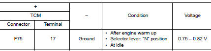
Is the inspection result normal? YES >> INSPECTION END
NO >> GO TO 2.
2.CHECK PRIMARY PRESSURE SENSOR POWER CIRCUIT
- Turn ignition switch OFF.
- Connect TCM connector.
- Disconnect CVT unit connector.
- Check voltage between CVT unit harness connector terminal and ground.
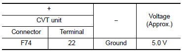
Is the inspection result normal? YES >> GO TO 3.
NO >> Repair or replace malfunctioning parts.
3.CHECK PRIMARY PRESSURE SENSOR SIGNAL CIRCUIT
Check voltage between CVT unit harness connector terminal and ground.
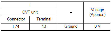
Is the inspection result normal? YES >> There is malfunction of primary pressure sensor. Replace transaxle assembly. Refer to TM-220, "Removal and Installation".
NO >> Repair or replace malfunctioning parts.
 P084c transmission fluid pressure SEN/SW H
DTC Description
DTC DETECTION LOGIC
DTC
CONSULT screen terms
(Trouble diagnosis content)
DTC detection condition
P084C
FLUID PRESS SEN/SW H
(Transmission Fluid Pressur ...
 P0863 TCM communication
DTC Description
DTC DETECTION LOGIC
DTC
CONSULT screen terms
(Trouble diagnosis content)
DTC detection condition
P0863
CONTROL UNIT (CAN)
(TCM Communication Circuit)
...
Other materials:
Symptom diagnosis
HEATER AND AIR CONDITIONING SYSTEM CONTROL SYMPTOMS
Symptom Table
SYMPTOM TABLE
Symptom
Reference Page
A/C system does not come on.
Go to Trouble Diagnosis Procedure for A/C System.
HAC-166, "FRONT
A/C CONTROL : Diagnosis
Procedure"
Air ou ...
Manual control
While using the Voice Recognition system, it is
possible to select menu options by using the
steering wheel controls instead of speaking voice
commands. To activate manual control mode,
press the PHONE/SEND ( ) button on
the
steering wheel to access the phone menu and
then press either u ...
Side air bag (satellite) sensor
Exploded View
Front door satellite sensor
Front side air bag satellite sensor
Rear side satellite sensor
Satellite sensor harness connector
Bolt
Nut
Pawl
Front
NOTE:
RH side shown, LH side similar.
Removal and Installation
WARNING:
Bef ...
