Nissan Rogue Service Manual: Parking brake front cable
Removal and Installation
REMOVAL
- Remove the instrument lower panel LH. Refer to IP-22, "Removal and Installation".
- Remove driver seat (LH). Refer to SE-32, "DRIVER SIDE : Removal and Installation"
- Remove the center console. Refer to IP-18, "Removal and Installation".
- Remove the parking brake control. Refer to PB-7, "Removal and Installation"
- Remove front door welts (LH). Refer to INT-23, "BODY SIDE WELT : Removal and Installation - Front Door Welt".
- Remove dash side finisher (LH). Refer to INT-24, "DASH SIDE FINISHER : Removal and Installation".
- Remove shift selector. Refer to TM-194, "Removal and Installation".
- Remove the front floor connecting ducts (LH/RH). Refer to VTL-10, "FRONT FLOOR DUCT : Removal and Installation - Front Floor Connecting Duct".
- Remove the front floor duct. Refer to VTL-11, "FRONT FLOOR DUCT : Removal and Installation - Front Floor Duct"
- Remove the rear center ventilator duct. Refer to VTL-11, "REAR CENTER VENTILATOR DUCT : Removal and Installation".
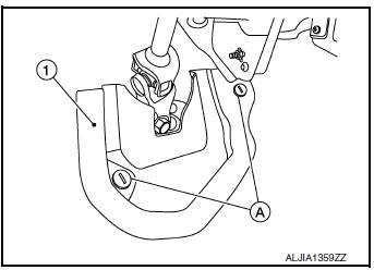
- Release clips (A) using a suitable tool and remove steering joint floor cover (1).
- Place front floor trim aside and remove the front floor spacer. Refer to INT-26, "Exploded View".
- Remove the bolts from the parking brake front cable mount. Refer to PB-7, "Exploded View".
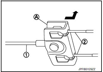
- Pull equalizer (A) of the parking brake front cable (1) in a
rearward
direction and then push upward to separate each parking
brake rear cable (2) from the parking brake front cable (1).
CAUTION: To prevent damage to the parts, do not bend the parking brake cables.
- Remove the parking brake front cable.
INSTALLATION
Installation is in the reverse order of removal.
CAUTION: Do not reuse the adjusting nut.
- Inspect and adjust the parking brake pedal. Refer to PB-4, "Inspection and Adjustment".
 Parking brake control
Exploded View
Parking brake rear cable (RH)
Parking brake rear cable (LH)
Parking brake front cable
Parking brake control
Adjusting nut
Parking brake switch
Removal and ...
 Parking brake rear cable
Removal and Installation
REMOVAL
Remove the center console assembly. Refer to IP-18, "Removal and
Installation".
Remove shift selector. Refer to TM-194, "Removal a ...
Other materials:
Symptom diagnosis
EXTERIOR LIGHTING SYSTEM SYMPTOMS
Symptom Table
CAUTION:
Perform the self-diagnosis with CONSULT before the symptom diagnosis. Perform
the trouble diagnosis
if any DTC is detected.
NORMAL OPERATING CONDITION
Description
AUTO LIGHT SYSTEM
The headlamp may not be turned ON/OFF immedi ...
Back door outer finisher
Exploded View
Back door outer finisher
License lamp finisher
Clip
Removal and Installation
REMOVAL
Remove back door finisher. Refer to INT-38, "Removal and Installation".
Remove plugs (A) from back door (1).
Remove back door outer finisher nuts.
...
AM radio reception
AM signals, because of their low frequency, can
bend around objects and skip along the ground.
In addition, the signals can be bounced off the
ionosphere and bent back to earth. Because of
these characteristics, AM signals are also subject
to interference as they travel from transmitter
to r ...
