Nissan Rogue Service Manual: Fuel level sensor signal circuit
Component Function Check
1.COMBINATION METER INPUT SIGNAL
- Select "METER/M&A" on "CONSULT".
- Using "FUEL METER" of "Data Monitor", compare the value of "Data Monitor" with fuel gauge pointer of combination meter.
Does the data monitor value approximately match the fuel gauge indication? YES >> Inspection End.
NO >> Replace combination meter. Refer to MWI-82, "Removal and Installation".
Diagnosis Procedure
1.CHECK FUEL LEVEL SENSOR UNIT AND FUEL PUMP (FUEL LEVEL SENSOR) CIRCUIT
- Turn ignition switch OFF.
- Disconnect combination meter connector and fuel level sensor unit and fuel pump (fuel level sensor) connector.
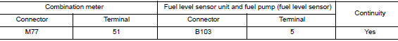
- Check continuity between combination meter harness connector and fuel level sensor unit and fuel pump (fuel level sensor) harness connector.
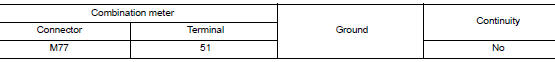
- Check continuity between combination meter harness connector and ground.
Is the inspection result normal? YES >> GO TO 2.
NO >> Repair harness or connector.
2.CHECK FUEL LEVEL SENSOR UNIT AND FUEL PUMP (FUEL LEVEL SENSOR) GROUND CIRCUIT
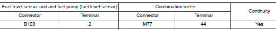
Check continuity between fuel level sensor unit and fuel pump (fuel level sensor) harness connector and combination meter harness connector.
Is the inspection result normal? YES >> Replace combination meter. Refer to MWI-82, "Removal and Installation".
NO >> Repair harness or connector.
Component Inspection
1.CHECK FUEL LEVEL SENSOR UNIT AND FUEL PUMP (FUEL LEVEL SENSOR)
- Remove the fuel level sensor unit and fuel pump (fuel level sensor). Refer to FL-6, "Removal and Installation".
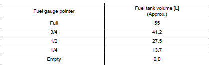
- Check the resistance between fuel level sensor unit and fuel pump (fuel level sensor).
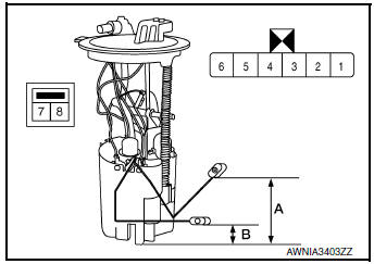
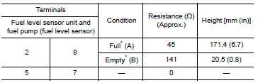
*: When float rod is contact with stopper.
Is the inspection result normal? YES >> GO TO 2.
NO >> Replace fuel level sensor unit and fuel pump (fuel level sensor). Refer to FL-6, "Removal and Installation".
2.CHECK FUEL LEVEL SENSOR UNIT (SUB)
- Remove the fuel level sensor unit (sub). Refer to FL-6, "Removal and Installation".
- Check the resistance between fuel level sensor unit (sub).
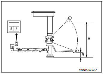
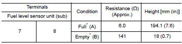
*: When float rod is contact with stopper.
Is the inspection result normal? YES >> Inspection End.
NO >> Replace fuel level sensor unit (sub). Refer to FL-6, "Removal and Installation".
 Power supply and ground circuit
COMBINATION METER
COMBINATION METER : Diagnosis Procedure
Regarding Wiring Diagram information, refer to MWI-32, "Wiring Diagram".
1.CHECK FUSES
Check that the following fuses are not bl ...
 Parking brake switch signal circuit
Description
Transmits the parking brake switch signal to the combination meter.
Component Function Check
1.COMBINATION METER INPUT SIGNAL
Start engine.
Check "PKB SW" in ...
Other materials:
Precaution
Precaution for Supplemental Restraint System (SRS) "AIR BAG" and "SEAT
BELT
PRE-TENSIONER"
The Supplemental Restraint System such as “AIR BAG” and “SEAT BELT PRE-TENSIONER”,
used along
with a front seat belt, helps to reduce the risk or severity of injury to the
...
Rear window defogger switch
WITH MANUAL A/C
WITH MANUAL A/C : Description
The rear window defogger is operated by pressing the rear window
defogger switch ON.
The indicator lamp in the rear window defogger switch illuminates
while the rear window defogger is ON.
WITH MANUAL A/C : Component Function Check
...
ECU diagnosis information
CHASSIS CONTROL MODULE
Reference Value
CONSULT DATA MONITOR STANDARD VALUE
NOTE:
The following table includes information (items) inapplicable to this vehicle.
For information (items) applicable
to this vehicle, refer to CONSULT display items.
*: Check tire pressure under ...
