Nissan Rogue Service Manual: Power supply and ground circuit
COMBINATION METER
COMBINATION METER : Diagnosis Procedure
Regarding Wiring Diagram information, refer to MWI-32, "Wiring Diagram".
1.CHECK FUSES
Check that the following fuses are not blown.
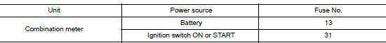
Is the fuse blown? YES >> Replace the blown fuse after repairing the affected circuit.
NO >> GO TO 2.
2.POWER SUPPLY CIRCUIT CHECK
- Disconnect combination meter connector.
- Check voltage between combination meter harness connector M77 terminals 45, 46 and ground.
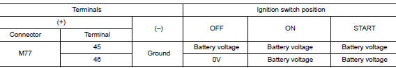
Is the inspection result normal? YES >> GO TO 3.
NO >> Repair or replace harness or connector.
3.GROUND CIRCUIT CHECK
- Turn ignition switch OFF.
- Check continuity between combination meter harness connector and ground.
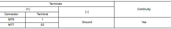
Is the inspection result normal? YES >> Inspection End.
NO >> Repair or replace harness or connector.
BCM (BODY CONTROL SYSTEM) (WITH INTELLIGENT KEY SYSTEM)
BCM (BODY CONTROL SYSTEM) (WITH INTELLIGENT KEY SYSTEM) : Diagnosis Procedure
Regarding Wiring Diagram information, refer to BCS-50, "Wiring Diagram".
1. CHECK FUSE
Check that the following fuse is not blown.

Is the fuse blown? YES >> Replace the blown fuse after repairing the affected circuit.
NO >> GO TO 2.
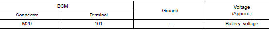
2. CHECK POWER SUPPLY CIRCUIT
- Disconnect BCM connector M20.
- Check voltage between BCM connector M20 and ground.
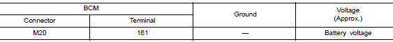
Is the inspection result normal? YES >> GO TO 3.
NO >> Repair or replace harness or connectors.
3. CHECK GROUND CIRCUIT
Check continuity between BCM connector M20 and ground.
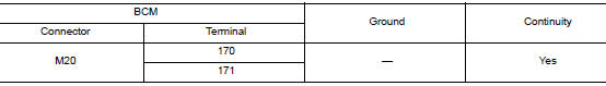
Is the inspection result normal? YES >> Inspection End.
NO >> Repair or replace harness or connectors.
BCM (BODY CONTROL SYSTEM) (WITHOUT INTELLIGENT KEY SYSTEM)
BCM (BODY CONTROL SYSTEM) (WITHOUT INTELLIGENT KEY SYSTEM) : Diagnosis Procedure
Regarding Wiring Diagram information, refer to BCS-110, "Wiring Diagram".
1. CHECK FUSE
Check that the following fuse is not blown.

Is the fuse blown? YES >> Replace the blown fuse after repairing the affected circuit.
NO >> GO TO 2.
2. CHECK POWER SUPPLY CIRCUIT
- Disconnect BCM connector M20.
- Check voltage between BCM connector M20 and ground.
Is the inspection result normal? YES >> GO TO 3.
NO >> Repair or replace harness or connectors.
3. CHECK GROUND CIRCUIT
Check continuity between BCM connector M20 and ground.
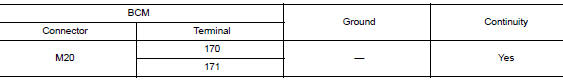
Is the inspection result normal? YES >> Inspection End.
NO >> Repair or replace harness or connectors.
 B2268 water temp
Description
The engine coolant temperature signal is transmitted from ECM to the
combination meter via CAN communication.
DTC Logic
DTC DETECTION LOGIC
DTC
CONSULT
Detec ...
 Fuel level sensor signal circuit
Component Function Check
1.COMBINATION METER INPUT SIGNAL
Select "METER/M&A" on "CONSULT".
Using "FUEL METER" of "Data Monitor", compare ...
Other materials:
P052A, P052B intake valve timing control
DTC Description
DTC DETECTION LOGIC
DTC No.
CONSULT screen terms
(Trouble diagnosis content)
DTC detecting condition
P052A
CAMSHAFT POSITION TIMING B1
(Cold start “A” camshaft position timing
over-advanced bank 1)
There is a gap between angle of target and ...
Removal and installation
BCM (BODY CONTROL MODULE)
Removal and Installation
CAUTION:
Before replacing the BCM, perform “READ CONFIGURATION” to save or print current
vehicle specification.
Refer to BCS-60, "ADDITIONAL SERVICE WHEN REPLACING CONTROL UNIT (BCM) : Work
Procedure".
REMOVAL
Disco ...
Power supply and ground circuit
COMBINATION METER
COMBINATION METER : Diagnosis Procedure
Regarding Wiring Diagram information, refer to MWI-32, "Wiring Diagram".
1.CHECK FUSES
Check that the following fuses are not blown.
Is the fuse blown?
YES >> Replace the blown fuse after repairing the affected circu ...
