Nissan Rogue Service Manual: Removal and installation
BCM (BODY CONTROL MODULE)
Removal and Installation
CAUTION: Before replacing the BCM, perform ŌĆ£READ CONFIGURATIONŌĆØ to save or print current vehicle specification.
Refer to BCS-60, "ADDITIONAL SERVICE WHEN REPLACING CONTROL UNIT (BCM) : Work Procedure".
REMOVAL
- Disconnect the negative battery terminal. Refer to PG-77, "Removal and Installation".
- Remove the instrument lower panel LH. Refer to IP-22, "Removal and Installation".
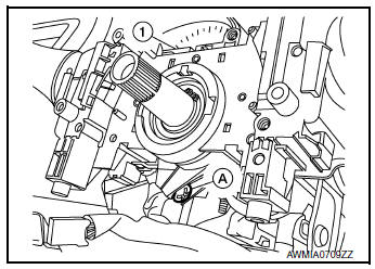
- Remove the bolt (A), then pull out the BCM (1).
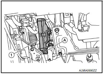
- Disconnect the harness connectors from the BCM and remove.
INSTALLATION
Installation is in the reverse order of removal.
CAUTION:
- When replacing BCM, perform ŌĆ£WRITE CONFIGURATIONŌĆØ Refer to BCS-61, "CONFIGURATION (BCM) : Work Procedure".
- When replacing BCM, perform the system initialization (NATS). Refer to the CONSULT immobilizer mode and follow the on-screen instructions.
- When replacing BCM, if new BCM does not come with keyfobs attached, all existing keyfobs must be re-registered. Refer to the CONSULT immobilizer mode and follow the on screen instructions.
COMBINATION SWITCH
Exploded View
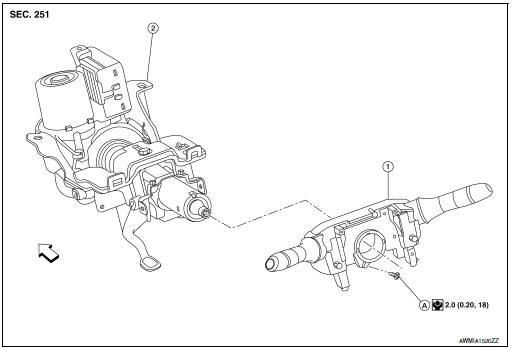
- Combination switch
- Steering column
- Screw
 Front
Front
Removal and Installation
REMOVAL
- Remove the steering angle sensor. Refer to BRC-139, "Removal and Installation".
- Disconnect harness connector from combination switch.
- Remove screw (A) and combination switch (1).
INSTALLATION
Installation is in the reverse order of removal.
 Symptom diagnosis
COMBINATION SWITCH SYSTEM SYMPTOMS
Symptom Table
Perform the data monitor of CONSULT to check for any malfunctioning
item.
Check the malfunction combinations.
Identify the malfunct ...

Other materials:
System description
COMPONENT PARTS
Component Parts Location
Right rear wheel area
Instrument panel
Engine compartment
Left side of instrument panel (view
with trim panel removed)
No.
Part
Function
1
Optical sensor
Refer to EXL-140, "Optical Senso ...
CVT fluid cooler system
Cleaning
Whenever an automatic transaxle is repaired, overhauled, or replaced, the CVT
fluid cooler mounted in the
radiator must be inspected and cleaned.
Metal debris and friction material, if present, can be trapped or be deposited
in the CVT fluid cooler. This
debris can contaminate the ...
System description
COMPONENT PARTS
BODY CONTROL SYSTEM
BODY CONTROL SYSTEM : Component Parts Location
BCM
Behind instrument panel (LH)
POWER CONSUMPTION CONTROL SYSTEM
POWER CONSUMPTION CONTROL SYSTEM : Component Parts Location
Combination meter
Refer to MWI-6, "METER SYSTEM :
Componen ...
