Nissan Rogue Service Manual: Parking brake switch signal circuit
Description
Transmits the parking brake switch signal to the combination meter.
Component Function Check
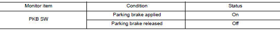
1.COMBINATION METER INPUT SIGNAL
- Start engine.
- Check "PKB SW" in "Data Monitor" while applying and releasing the parking brake.
Is the inspection result normal? YES >> Inspection End.
NO >> Refer to MWI-64, "Diagnosis Procedure".
Diagnosis Procedure
Regarding Wiring Diagram information, refer to MWI-32, "Wiring Diagram".
1.CHECK PARKING BRAKE SWITCH CIRCUIT
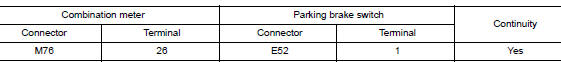
- Disconnect combination meter harness connector M76 and parking brake switch harness connector E52.
- Check continuity between combination meter harness connector M76 terminal 26 and parking brake switch harness connector E52 terminal 1.
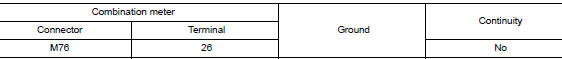
- Check continuity between combination meter harness connector M76 terminal 26 and ground.
Is the inspection result normal? YES >> Inspection End.
NO >> Repair or replace harness or connector.
Component Inspection
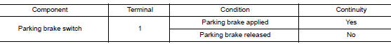
1.CHECK PARKING BRAKE SWITCH
Check continuity between parking brake switch terminal 1 and switch case ground.
Is the inspection result normal? YES >> Inspection End.
NO >> Replace parking brake switch. Refer to PB-7, "Exploded View".
 Fuel level sensor signal circuit
Component Function Check
1.COMBINATION METER INPUT SIGNAL
Select "METER/M&A" on "CONSULT".
Using "FUEL METER" of "Data Monitor", compare ...
 Ambient sensor signal circuit
Description
It detects outside air temperature and converts it into a resistance value
which is then input into the combination
meter.
Diagnosis Procedure
Regarding Wiring Diagram information, r ...
Other materials:
Preparation
Special Service Tools
The actual shape of the tools may differ from those illustrated here.
Tool number
(TechMate No.)
Tool name
Description
—
(J-46534)
Trim Tool Set
Removing trim components
...
Quarter window glass
Exploded View
Quarter window glass
Quarter window glass molding
Body side outer
7.0 mm (0.28 in)
12.0 (0.47 in)
Adhesive
Clip
Removal and Installation
REMOVAL
Remove the luggage side upper finisher. Refer to INT-36, "LUGGAGE
SIDE UPPER FINISHER :
...
Power supply and ground circuit
COMBINATION METER
COMBINATION METER : Diagnosis Procedure
Regarding Wiring Diagram information, refer to MWI-32, "Wiring Diagram".
1.CHECK FUSES
Check that the following fuses are not blown.
Is the fuse blown?
YES >> Replace the blown fuse after repairing the affected circu ...
