Nissan Rogue Service Manual: ECU diagnosis information
CHASSIS CONTROL MODULE
Reference Value
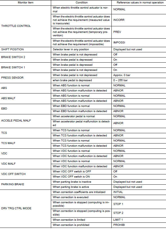
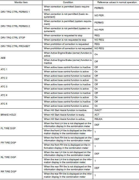
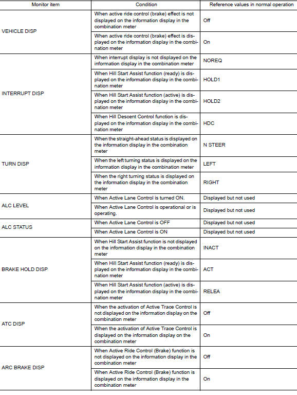
CONSULT DATA MONITOR STANDARD VALUE
NOTE: The following table includes information (items) inapplicable to this vehicle. For information (items) applicable to this vehicle, refer to CONSULT display items.
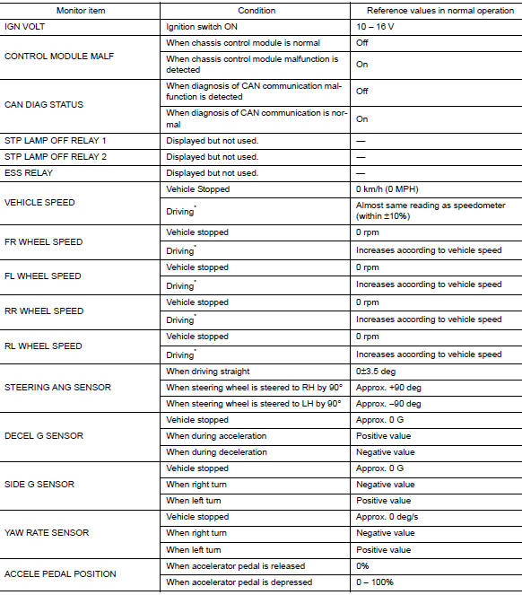
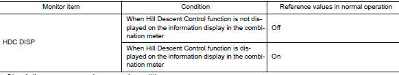
*: Check tire pressure under normal conditions.
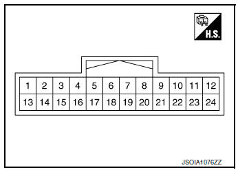
TERMINAL LAYOUT
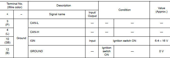
PHYSICAL VALUES
Fail-Safe (Chassis Control Module)
When a malfunction occurs in the chassis control module, the master warning lamp turns ON and an interrupt is displayed on the information display of the combination meter.
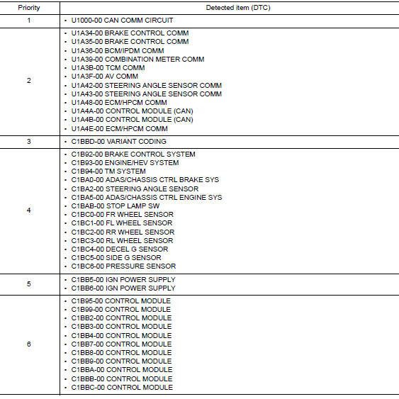
DTC Inspection Priority Chart
When multiple DTCs are displayed simultaneously, check them one by one according to the following priority list.
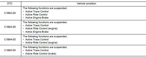
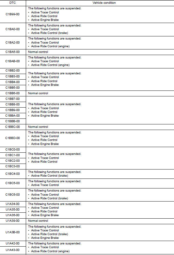
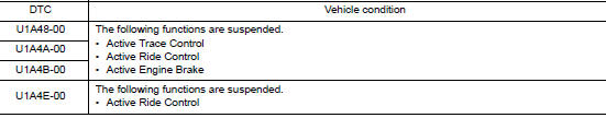
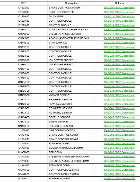
DTC Index
 System description
COMPONENT PARTS
Component Parts Location
Front of vehicle
Instrument panel LH
View with glove box removed
Rear of engine compartment RH
RH front of vehicle
Front of engine compar ...
 Wiring diagram
CHASSIS CONTROL
Wiring Diagram
...
Other materials:
Precaution
Precaution for Supplemental Restraint System (SRS) "AIR BAG" and "SEAT
BELT
PRE-TENSIONER"
The Supplemental Restraint System such as ŌĆ£AIR BAGŌĆØ and ŌĆ£SEAT BELT PRE-TENSIONERŌĆØ,
used along
with a front seat belt, helps to reduce the risk or severity of injury to the
...
U0141 lost communication (BCM A)
DTC Description
DTC DETECTION LOGIC
DTC
CONSULT screen terms
(Trouble diagnosis content)
DTC detection condition
U0141
LOST COMM (BCM A)
(Lost Communication With Body Control Module
A)
When the ignition switch is turned ON, TCM continues no reception of
the ...
Precaution]
Precaution for Supplemental Restraint System (SRS) "AIR BAG" and "SEAT
BELT
PRE-TENSIONER"
The Supplemental Restraint System such as ŌĆ£AIR BAGŌĆØ and ŌĆ£SEAT BELT PRE-TENSIONERŌĆØ,
used along
with a front seat belt, helps to reduce the risk or severity of injury to the
...
