Nissan Rogue Service Manual: DTC/circuit diagnosis
U0428 STEERING ANGLE SENSOR
DTC Logic
DTC DETECTION LOGIC
|
CONSULT Display |
DTC Detection Condition |
Possible Cause |
| ST ANG SEN CALIB [U0428] | Predictive course line center position adjustment of steering angle sensor is incomplete. | Adjust predictive course line center position adjustment of steering angle sensor. |
Diagnosis Procedure
1.ADJUST PREDICTIVE COURSE LINE CENTER POSITION ADJUSTMENT OF STEERING ANGLE SENSOR
When U0428 is detected, the predictive course line center position of steering angle sensor needs to be adjusted.
>> Adjust the predictive course line center position of steering angle sensor. Refer to AV-291, "PREDICTED COURSE LINE CENTER POSITION ADJUSTMENT : Work Procedure".
U1000 CAN COMM CIRCUIT
AV CONTROL UNIT
AV CONTROL UNIT : DTC Logic
DTC DETECTION LOGIC
|
CONSULT Display |
DTC Detection Condition |
Possible Cause |
| CAN COMM CIRCUIT [U1000] | AV control unit is not transmitting or receiving CAN communication signal for 2 seconds or more. | CAN communication system |
AV CONTROL UNIT : Diagnosis Procedure
1.PERFORM SELF DIAGNOSTIC RESULT
- Turn ignition switch ON and wait for 2 seconds or more.
- Perform “Self Diagnostic Result” for “MULTI AV”.
Is CAN COMM CIRCUIT displayed? YES >> Refer to LAN-17, "Trouble Diagnosis Flow Chart".
NO >> Refer to GI-41, "Intermittent Incident".
AROUND VIEW MONITOR CONTROL UNIT
AROUND VIEW MONITOR CONTROL UNIT : DTC Logic
DTC DETECTION LOGIC
|
CONSULT Display |
DTC Detection Condition |
Possible Cause |
| CAN COMM CIRCUIT [U1000] | Around view monitor control unit is not transmitting or receiving CAN communication signal for 2 seconds or more. | CAN communication system. |
AROUND VIEW MONITOR CONTROL UNIT : Diagnosis Procedure
1.PERFORM SELF DIAGNOSTIC RESULT
- Turn ignition switch ON and wait for 2 seconds or more.
- Perform “Self Diagnostic Result” for “AVM”.
Is CAN COMM CIRCUIT displayed? YES >> Refer to LAN-17, "Trouble Diagnosis Flow Chart".
NO >> Refer to GI-41, "Intermittent Incident".
U1010 CONTROL UNIT (CAN)
AV CONTROL UNIT
AV CONTROL UNIT : DTC Logic
DTC DETECTION LOGIC
|
CONSULT Display |
DTC Detection Condition |
Possible Cause |
| CONTROL UNIT (CAN) [U1010] | Error during CAN controller hardware initialization (VCAN). | Replace the AV control unit if the malfunction occurs
constantly.
Refer to AV-376, "Removal and Installation". |
AROUND VIEW MONITOR CONTROL UNIT
AROUND VIEW MONITOR CONTROL UNIT : DTC Logic
DTC DETECTION LOGIC
|
CONSULT Display |
DTC Detection Condition |
Possible Cause |
| CONTROL UNIT (CAN) [U1010] | Error during CAN controller hardware initialization (VCAN). | Replace the Around view monitor control unit if
the malfunction occurs constantly.
Refer to AV-387, "Removal and Installation". |
U111A REAR CAMERA IMAGE SIGNAL CIRCUIT
DTC Logic
DTC DETECTION LOGIC
|
CONSULT Display |
DTC Detection Condition |
Possible Cause |
| Rear display output signal diagnosis (Harness disconnection) [U111A] | Rear view camera image signal circuit open or short. | Check rear view camera image signal circuit. |
Diagnosis Procedure
Regarding Wiring Diagram information, refer to AV-262, "Wiring Diagram".
WITHOUT DRIVER ASSISTANCE SYSTEM
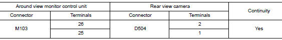
1.CHECK REAR VIEW CAMERA POWER SUPPLY AND GROUND CIRCUIT CONTINUITY
- Turn ignition switch OFF.
- Disconnect around view monitor control unit and rear view camera connectors.
- Check continuity between around view monitor control unit connector M103 and rear view camera connector D504.
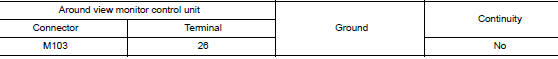
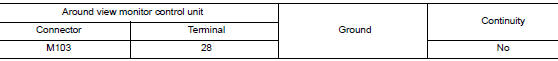
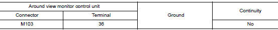
- Check continuity between around view monitor control unit connector M103 and ground.
Is the inspection result normal? YES >> GO TO 2.
NO >> Repair or replace harness or connectors.
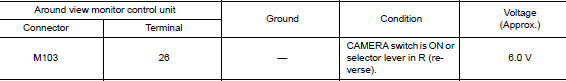
2.CHECK REAR VIEW CAMERA POWER SUPPLY VOLTAGE
- Connect around view monitor control unit and rear view camera connectors.
- Turn ignition switch ON.
- Check voltage between around view monitor control unit connector M103 and ground.
Is the inspection result normal? YES >> GO TO 3.
NO >> Replace around view monitor control unit. Refer to AV-387, "Removal and Installation".
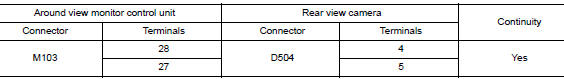
3.CHECK REAR VIEW CAMERA IMAGE SIGNAL AND IMAGE SIGNAL GROUND CIRCUIT CONTINUITY
- Turn ignition switch OFF.
- Disconnect around view monitor control unit and rear view camera connectors.
- Check continuity between around view monitor control unit connector M103 and rear view camera connector D504.
- Check continuity between around view monitor control unit connector M103 and ground.
Is the inspection result normal? YES >> GO TO 4.
NO >> Repair or replace harness or connectors.
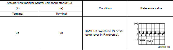
4.CHECK REAR VIEW CAMERA IMAGE SIGNAL
- Connect around view monitor control unit and rear view camera connectors.
- Turn ignition switch ON.
- Check signal between the terminals of around view monitor control unit connector M103.
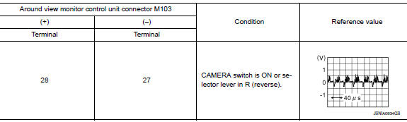
Is the inspection result normal? YES >> Replace around view monitor control unit. Refer to AV-387, "Removal and Installation".
NO >> Replace rear view camera. Refer to AV-390, "Removal and Installation".
WITH DRIVER ASSISTANCE SYSTEM
1.CHECK REAR VIEW CAMERA POWER SUPPLY AND GROUND CIRCUIT CONTINUITY
- Turn ignition switch OFF.
- Disconnect around view monitor control unit and rear view camera connectors.
- Check continuity between around view monitor control unit connector M114 and rear view camera connector D514.
- Check continuity between around view monitor control unit connector M114 and ground.
Is the inspection result normal? YES >> GO TO 2.
NO >> Repair or replace harness or connectors.
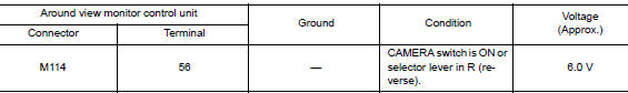
2.CHECK REAR VIEW CAMERA POWER SUPPLY VOLTAGE
- Connect around view monitor control unit and rear view camera connectors.
- Turn ignition switch ON.
- Check voltage between around view monitor control unit connector M114 and ground.
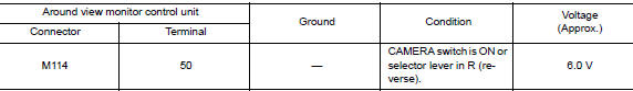
Is the inspection result normal? YES >> GO TO 3.
NO >> Replace around view monitor control unit. Refer to AV-387, "Removal and Installation".
3.CHECK REAR VIEW CAMERA IMAGE SIGNAL AND IMAGE SIGNAL GROUND CIRCUIT CONTINUITY
- Turn ignition switch OFF.
- Disconnect around view monitor control unit and rear view camera connectors.
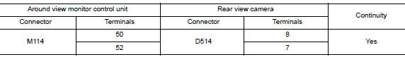
- Check continuity between around view monitor control unit connector M114 and rear view camera connector D514.
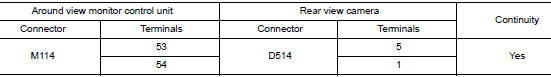
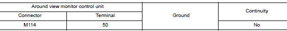
- Check continuity between around view monitor control unit connector M114 and ground.
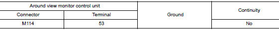
Is the inspection result normal? YES >> GO TO 4.
NO >> Repair or replace harness or connectors.
4.CHECK REAR VIEW CAMERA IMAGE SIGNAL
- Connect around view monitor control unit and rear view camera connectors.
- Turn ignition switch ON.
- . Check signal between the terminals of around view monitor control unit connector M114.
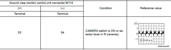
Is the inspection result normal? YES >> Replace around view monitor control unit. Refer to AV-387, "Removal and Installation".
NO >> Replace rear view camera. Refer to AV-390, "Removal and Installation".
U111B SIDE CAMERA RH IMAGE SIGNAL CIRCUIT
DTC Logic
DTC DETECTION LOGIC
|
CONSULT Display |
DTC Detection Condion |
Possible Cause |
| Right side display output signal diagnosis (Harness disconnection) [U111B] | Right side camera image signal circuit open or short. | Check right side camera image signal circuit. |
Diagnosis Procedure
Regarding Wiring Diagram information, refer to AV-262, "Wiring Diagram".
WITHOUT DRIVER ASSISTANCE SYSTEM
1.CHECK RH SIDE CAMERA POWER SUPPLY AND GROUND CIRCUIT CONTINUITY
- Turn ignition switch OFF.
- Disconnect around view monitor control unit and RH side camera connectors.
- Check contin
- Check continuity between around view monitor control unit connector M103 and ground.
Is the inspection result normal? YES >> GO TO 2.
NO >> Repair or replace harness or connectors.
2.CHECK RH SIDE CAMERA POWER SUPPLY VOLTAGE
- Connect around view monitor control unit and RH side camera connectors.
- Turn ignition switch ON.
- Check voltage between around view monitor control unit connector M103 and ground.
Is the inspection result normal? YES >> GO TO 3.
NO >> Replace around view monitor control unit. Refer to AV-387, "Removal and Installation".
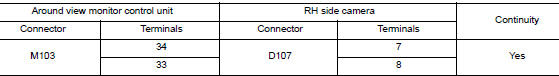
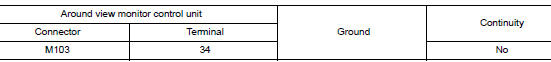
3.CHECK RH SIDE CAMERA IMAGE SIGNAL AND IMAGE SIGNAL GROUND CIRCUIT CONTINUITY
- Turn ignition switch OFF.
- Disconnect around view monitor control unit and RH side camera connectors.
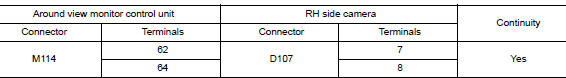
- Check continuity between around view monitor control unit connector M103 and RH side camera connector D107.
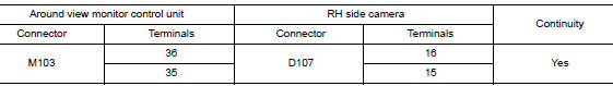
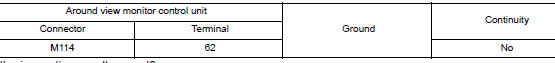
- Check continuity between around view monitor control unit connector M103 and ground.
Is the inspection result normal? YES >> GO TO 4.
NO >> Repair or replace harness or connectors.
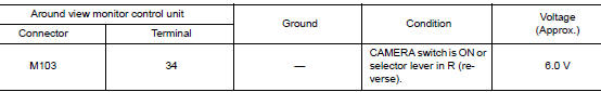
4.CHECK RH SIDE CAMERA IMAGE SIGNAL
- Connect around view monitor control unit and RH side camera connectors.
- Turn ignition switch ON.
- Check signal between the terminals of around view monitor control unit connector M103.
Is the inspection result normal? YES >> Replace around view monitor control unit. Refer to AV-387, "Removal and Installation".
NO >> Replace RH side camera. Refer to AV-389, "Removal and Installation".
WITH DRIVER ASSISTANCE SYSTEM
1.CHECK RH SIDE CAMERA POWER SUPPLY AND GROUND CIRCUIT CONTINUITY
- Turn ignition switch OFF.
- Disconnect around view monitor control unit and RH side camera connectors.
- Check continuity between around view monitor control unit connector M114 and RH side camera connector D107.
- Check continuity between around view monitor control unit connector M114 and ground.
Is the inspection result normal? YES >> GO TO 2.
NO >> Repair or replace harness or connectors.
2.CHECK RH SIDE CAMERA POWER SUPPLY VOLTAGE
- Connect around view monitor control unit and RH side camera connectors.
- Turn ignition switch ON.
- Check voltage between around view monitor control unit connector M114 and ground.
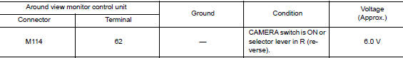
Is the inspection result normal? YES >> GO TO 3.
NO >> Replace around view monitor control unit. Refer to AV-387, "Removal and Installation".
3.CHECK RH SIDE CAMERA IMAGE SIGNAL AND IMAGE SIGNAL GROUND CIRCUIT CONTINUITY
- Turn ignition switch OFF.
- Disconnect around view monitor control unit and RH side camera connectors.
- Check continuity between around view monitor control unit connector M114 and RH side camera connector D107.
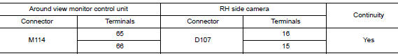
- Check continuity between around view monitor control unit connector M114 and ground.
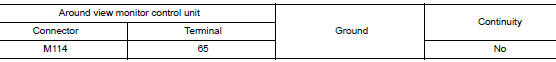
Is the inspection result normal? YES >> GO TO 4.
NO >> Repair or replace harness or connectors.
4.CHECK RH SIDE CAMERA IMAGE SIGNAL
- Connect around view monitor control unit and RH side camera connectors.
- Turn ignition switch ON.
- Check signal between the terminals of around view monitor control unit connector M114.
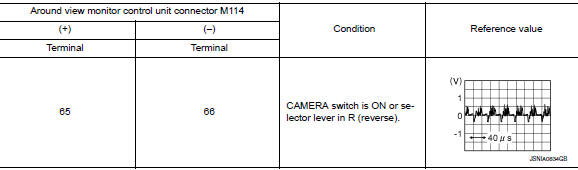
Is the inspection result normal? YES >> Replace around view monitor control unit. Refer to AV-387, "Removal and Installation".
NO >> Replace RH side camera. Refer to AV-389, "Removal and Installation".
U111C FRONT CAMERA IMAGE SIGNAL CIRCUIT
DTC Logic
DTC DETECTION LOGIC
|
CONSULT Display |
DTC Detection Condition |
Possible Cause |
| Front display output signal diagnosis (Harness disconnection) [U111C] | Front camera image signal circuit open or short. | Check front camera image signal circuit. |
Diagnosis Procedure
Regarding Wiring Diagram information, refer to AV-262, "Wiring Diagram".
WITHOUT DRIVER ASSISTANCE SYSTEM
1.CHECK FRONT CAMERA POWER SUPPLY AND GROUND CIRCUIT CONTINUITY
- Turn ignition switch OFF.
- Disconnect around view monitor control unit and front camera connectors.
- Check continuity between around view monitor control unit connector M103 and front camera connector E226.
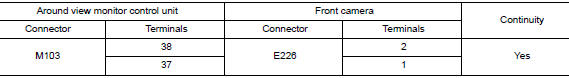
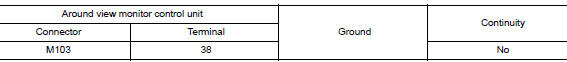
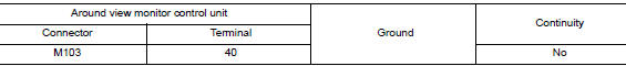
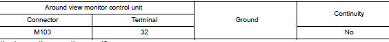
- Check continuity between around view monitor control unit connector M103 and ground.
Is the inspection result normal? YES >> GO TO 2.
NO >> Repair or replace harness or connectors.
2.CHECK FRONT CAMERA POWER SUPPLY VOLTAGE
- Connect around view monitor control unit and front camera connectors.
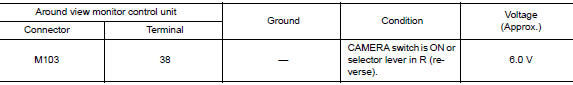
- Turn ignition switch ON.
- Check voltage between around view monitor control unit connector M103 and ground.
Is the inspection result normal? YES >> GO TO 3.
NO >> Replace around view monitor control unit. Refer to AV-387, "Removal and Installation".
3.CHECK FRONT CAMERA IMAGE SIGNAL AND IMAGE SIGNAL GROUND CIRCUIT CONTINUITY
- Turn ignition switch OFF.
- Disconnect around view monitor control unit and front camera connectors.
- Check continuity between around view monitor control unit connector M103 and front camera connector E226.
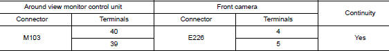
- Check continuity between around view monitor control unit connector M103 and ground.
Is the inspection result normal? YES >> GO TO 4.
NO >> Repair or replace harness or connectors.
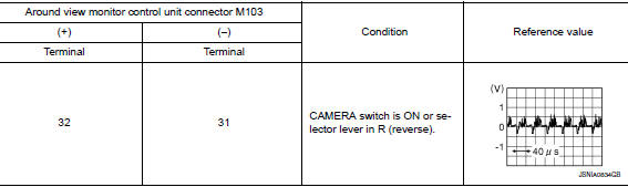
4.CHECK FRONT CAMERA IMAGE SIGNAL
- Connect around view monitor control unit and front camera connectors.
- Turn ignition switch ON.
- Check signal between the terminals of around view monitor control unit connector M103.
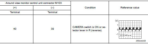
Is the inspection result normal? YES >> Replace around view monitor control unit. Refer to AV-387, "Removal and Installation".
NO >> Replace front camera. Refer to AV-388, "Removal and Installation".
WITH DRIVER ASSISTANCE SYSTEM
1.CHECK FRONT CAMERA POWER SUPPLY AND GROUND CIRCUIT CONTINUITY
- Turn ignition switch OFF.
- Disconnect around view monitor control unit and front camera connectors.
- Check continuity between around view monitor control unit connector M114 and front camera connector E226.
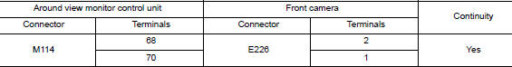
- Check continuity between around view monitor control unit connector M114 and ground.
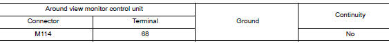
Is the inspection result normal? YES >> GO TO 2.
NO >> Repair or replace harness or connectors.
2.CHECK FRONT CAMERA POWER SUPPLY VOLTAGE
- Connect around view monitor control unit and front camera connectors.
- Turn ignition switch ON.
- Check voltage between around view monitor control unit connector M114 and ground.
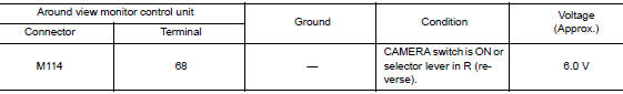
Is the inspection result normal? YES >> GO TO 3.
NO >> Replace around view monitor control unit. Refer to AV-387, "Removal and Installation".
3.CHECK FRONT CAMERA IMAGE SIGNAL AND IMAGE SIGNAL GROUND CIRCUIT CONTINUITY
- Turn ignition switch OFF.
- Disconnect around view monitor control unit and front camera connectors.
- Check continuity between around view monitor control unit connector M114 and front camera connector E226.
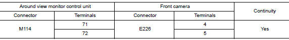
- Check continuity between around view monitor control unit connector M114 and ground.
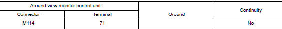
Is the inspection result normal? YES >> GO TO 4.
NO >> Repair or replace harness or connectors.
4.CHECK FRONT CAMERA IMAGE SIGNAL
- Connect around view monitor control unit and front camera connectors.
- Turn ignition switch ON.
- Check signal between the terminals of around view monitor control unit connector M114.
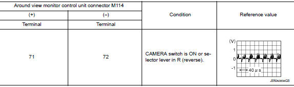
Is the inspection result normal? YES >> Replace around view monitor control unit. Refer to AV-387, "Removal and Installation".
NO >> Replace front camera. Refer to AV-388, "Removal and Installation".
U111D SIDE CAMERA LH IMAGE SIGNAL CIRCUIT
DTC Logic
DTC DETECTION LOGIC
|
CONSULT Display |
DTC Detection Condition |
Possible Cause |
| Left side display output signal diagnosis (Harness disconnection) [U111D] | Left side camera image signal circuit open or short. | Check left side camera image signal circuit. |
Diagnosis Procedure
Regarding Wiring Diagram information, refer to AV-262, "Wiring Diagram".
WITHOUT DRIVER ASSISTANCE SYSTEM
1.CHECK LH SIDE CAMERA POWER SUPPLY AND GROUND CIRCUIT CONTINUITY
- Turn ignition switch OFF.
- Disconnect around view monitor control unit and LH side camera connectors.
- Check continuity between around view monitor control unit connector M103 and LH side camera connector D14.
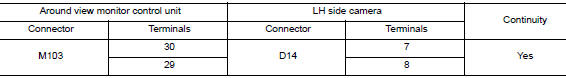
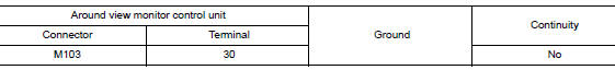
- Check continuity between around view monitor control unit connector M103 and ground.
Is the inspection result normal? YES >> GO TO 2.
NO >> Repair or replace harness or connectors.
2.CHECK LH SIDE CAMERA POWER SUPPLY VOLTAGE
- Connect around view monitor control unit and LH side camera connectors.
- Turn ignition switch ON.
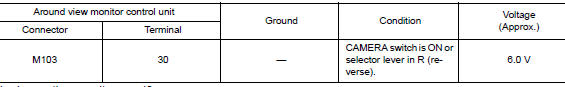
- Check voltage between around view monitor control unit connector M103 and ground.
Is the inspection result normal? YES >> GO TO 3.
NO >> Replace around view monitor control unit. Refer to AV-387, "Removal and Installation".
3.CHECK LH SIDE CAMERA IMAGE SIGNAL AND IMAGE SIGNAL GROUND CIRCUIT CONTINUITY
- Turn ignition switch OFF.
- Disconnect around view monitor control unit and LH side camera connectors.
- Check continuity between around view monitor control unit connector M103 and LH side camera connector D14.
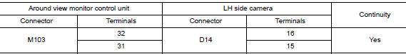
- Check continuity between around view monitor control unit connector M103 and ground.
Is the inspection result normal? YES >> GO TO 4.
NO >> Repair or replace harness or connectors.
4.CHECK LH SIDE CAMERA IMAGE SIGNAL
- Connect around view monitor control unit and LH side camera connectors.
- Turn ignition switch ON.
- Check signal between the terminals of around view monitor control unit connector M103.
Is the inspection result normal? YES >> Replace around view monitor control unit. Refer to AV-387, "Removal and Installation".
NO >> Replace LH side camera. Refer to AV-389, "Removal and Installation".
WITH DRIVER ASSISTANCE SYSTEM
1.CHECK LH SIDE CAMERA POWER SUPPLY AND GROUND CIRCUIT CONTINUITY
- Turn ignition switch OFF.
- Disconnect around view monitor control unit and LH side camera connectors.
- Check continuity between around view monitor control unit connector M114 and LH side camera connector D14.
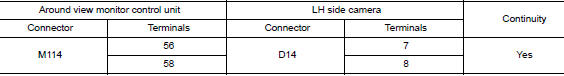
- Check continuity between around view monitor control unit connector M114 and ground.
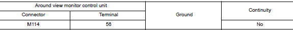
Is the inspection result normal? YES >> GO TO 2.
NO >> Repair or replace harness or connectors.
2.CHECK LH SIDE CAMERA POWER SUPPLY VOLTAGE
- Connect around view monitor control unit and LH side camera connectors.
- Turn ignition switch ON.
- Check voltage between around view monitor control unit connector M114 and ground.
Is the inspection result normal? YES >> GO TO 3.
NO >> Replace around view monitor control unit. Refer to AV-387, "Removal and Installation".
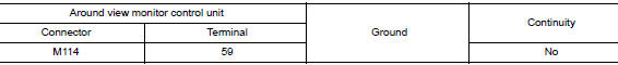
3.CHECK LH SIDE CAMERA IMAGE SIGNAL AND IMAGE SIGNAL GROUND CIRCUIT CONTINUITY
- Turn ignition switch OFF.
- Disconnect around view monitor control unit and LH side camera connectors.
- Check continuity between around view monitor control unit connector M114 and LH side camera connector D14.
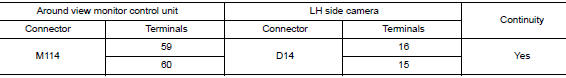
- Check continuity between around view monitor control unit connector M114 and ground.
Is the inspection result normal? YES >> GO TO 4.
NO >> Repair or replace harness or connectors.
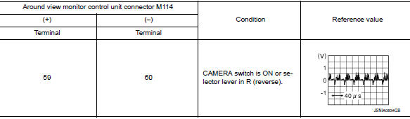
4.CHECK LH SIDE CAMERA IMAGE SIGNAL
- Connect around view monitor control unit and LH side camera connectors.
- Turn ignition switch ON.
- Check signal between the terminals of around view monitor control unit connector M114.
Is the inspection result normal? YES >> Replace around view monitor control unit. Refer to AV-387, "Removal and Installation".
NO >> Replace LH side camera. Refer to AV-389, "Removal and Installation".
U1217 AV CONTROL UNIT
DTC Logic
DTC DETECTION LOGIC
|
CONSULT Display |
DTC Detection Condition |
Possible Cause |
| BLUETOOTH MODULE [U1217] | Connection failure to the internal Blueooth® sub unit is detected. | Replace AV control unit if malfunction occurs
constantly. Refer to AV-376, "Removal and Installation". |
U1229 AV CONTROL UNIT
DTC Logic
DTC DETECTION LOGIC
|
CONSULT Display |
DTC Detection Condition |
Possible Cause |
| iPod CERTIFICATION [U1229] | iPod authentication chip error. | Replace AV control unit if malfunction occurs
constantly. Refer to AV-376, "Removal and Installation". |
U122F AV CONTROL UNIT
DTC Logic
DTC DETECTION LOGIC
|
CONSULT Display |
DTC Detection Condition |
Possible Cause |
| Digital broadcasting connection error [U122F] | Communication error with digital audio broadcast module internal to AV control unit. | Replace AV control unit if malfunction occurs
constantly. Refer to AV-376, "Removal and Installation". |
U1232 STEERING ANGLE SENSOR
DTC Logic
DTC DETECTION LOGIC
|
CONSULT Display |
DTC Detection Condition |
Possible Cause |
| ST ANG SEN CALIB [U1232] | Predictive course line center position adjustment of steering angle sensor is incomplete. | Adjust predictive course line center position adjustment of steering angle sensor. |
Diagnosis Procedure
1.ADJUST PREDICTIVE COURSE LINE CENTER POSITION ADJUSTMENT OF STEERING ANGLE SENSOR
When U1232 is detected, the predictive course line center position of steering angle sensor needs to be adjusted.
>> Adjust the predictive course line center position of steering angle sensor. Refer to AV-291, "PREDICTED COURSE LINE CENTER POSITION ADJUSTMENT : Work Procedure".
U1244 GPS ANTENNA
DTC Logic
DTC DETECTION LOGIC
|
CONSULT Display |
DTC Detection Condition |
Possible Cause |
| GPS ANTENNA CONN [U1244] | Open or short to ground is detected in GPS antenna connection. |
|
Diagnosis Procedure
Regarding Wiring Diagram information, refer to AV-262, "Wiring Diagram".
1.GPS ANTENNA INSPECTION
Visually inspect the GPS antenna and antenna feeder. Refer to AV-391, "Removal and Installation".
Is inspection result normal? YES >> GO TO 2.
NO >> Repair or replace malfunctioning components.
2.CHECK AV CONTROL UNIT VOLTAGE
- Disconnect AV control unit connector M141.
- Turn ignition switch ON.
- Check voltage between AV control unit connector M141 and ground.
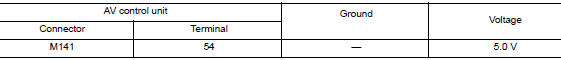
Is inspection result normal? YES >> Replace GPS antenna. Refer to AV-391, "Removal and Installation".
NO >> Replace AV control unit. Refer to AV-376, "Removal and Installation".
U1258 SATELLITE RADIO ANTENNA
DTC Logic
DTC DETECTION LOGIC
|
CONSULT Display |
DTC Detection Condition |
Possible Cause |
| SXM ANTENNA CONN [U1258] | Open or short to ground is detected in satellite antenna connection. |
|
Diagnosis Procedure
Regarding Wiring Diagram information, refer to AV-262, "Wiring Diagram".
1.SATELLITE ANTENNA INSPECTION
Visually inspect the satellite antenna and antenna feeder. Refer to AV-393, "Feeder Layout".
Is inspection result normal? YES >> GO TO 2.
NO >> Repair or replace malfunctioning components.
2.CHECK AV CONTROL UNIT VOLTAGE
- Turn ignition switch ON.
- Check voltage between AV control unit connector M142 and ground.
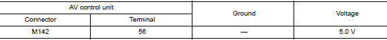
Is inspection result normal? YES >> Replace satellite radio antenna AV-392, "Removal and Installation".
NO >> Replace AV control unit. Refer to AV-376, "Removal and Installation".
U1263 USB
DTC Logic
DTC DETECTION LOGIC
|
CONSULT Display |
DTC Detection Condition |
Possible Cause |
| USB OVERCURRENT [U1263] | Overcurrent in USB harness is detected. |
|
DTC CONFIRMATION PROCEDURE
1.PERFORM SELF DIAGNOSTIC RESULT
- If there is a device connected to the USB interface, disconnect it.
- Turn ignition switch ON and wait for 2 seconds or more.
- Perform “Self Diagnostic Result” for “MULTI AV”.
Is DTC U1263 displayed? YES >> Refer to AV-322, "Diagnosis Procedure".
NO >> Inspection End.
Diagnosis Procedure
1.CHECK USB INTERFACE HARNESS
Visually inspect USB interface harness. Refer to AV-385, "Removal and Installation".
Is the inspection result normal? YES >> GO TO 2.
NO >> Replace USB interface harness. Refer to AV-385, "Removal and Installation".
2.CHECK USB INTERFACE HARNESS
Check USB interface harness. Refer to AV-359, "Diagnosis Procedure".
Is the inspection result normal? YES >> Replace AV control unit. Refer to AV-376, "Removal and Installation".
NO >> Replace USB interface harness. Refer to AV-385, "Removal and Installation".
U1265 BOSE AMP.
DTC Logic
|
CONSULT Display |
DTC Detection Condition |
Possible Cause |
| AMP ON TERMINAL [U1265] | Open or short to ground is detected in BOSE amp. ON signal circuit. | Open or short to ground in BOSE amp. ON signal circuit. |
Diagnosis Procedure
Regarding Wiring Diagram information, refer to AV-262, "Wiring Diagram".
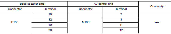
1.CHECK CONTINUITY BETWEEN AV CONTROL UNIT AND BOSE SPEAKER AMP.
- Turn ignition switch OFF.
- Disconnect AV control unit connector M108 and Bose speaker amp. connector B138
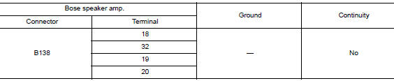
- Check continuity between AV control unit connector M108 and Bose speaker amp. connector B138.
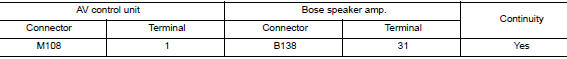
- Check continuity between AV control unit connector M108 and ground.
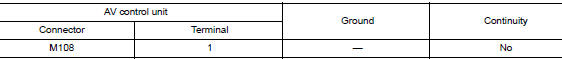
Is the inspection result normal? YES >> GO TO 2.
NO >> Repair or replace harness or connectors.
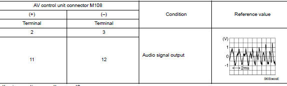
2.CHECK AV CONTROL UNIT VOLTAGE
- Connect AV control unit connector M108.
- Turn ignition switch ON.
- Check voltage between AV control unit connector M108 and ground.
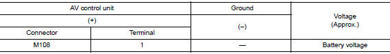
Is the inspection result normal? YES >> Replace Bose speaker amp. Refer to AV-379, "Removal and Installation".
NO >> Replace AV control unit. Refer to AV-376, "Removal and Installation".
U12AA CONFIGURATION ERROR
DTC Logic
DTC DETECTION LOGIC
|
CONSULT Display |
DTC Detection Condition |
Possible Cause |
| Configuration Error [U12AA] | AV control unit is not properly configured or configuration is corrupt. | Configuration data needs to be written. Refer to AV-289, "CONFIGURATION (AV CONTROL UNIT) : Work Procedure". |
Diagnosis Procedure
1.PERFORM CONFIGURATION
When U12AA is detected, configuration data must be written.
>> Write configuration data with CONSULT. Refer to AV-289, "CONFIGURATION (AV CONTROL UNIT) : Work Procedure".
U12AB ANTENNA
DTC Logic
DTC DETECTION LOGIC
|
CONSULT Display |
DTC Detection Condition |
Possible Cause |
| FM Antenna error [U12AB] | Open or short to ground is detected in AM-FM antenna connection. |
|
Diagnosis Procedure
Regarding Wiring Diagram information, refer to AV-262, "Wiring Diagram".
1.AM-FM ANTENNA INSPECTION
Visually inspect the antenna base (AM-FM antenna) and antenna feeder. Refer to AV-393, "Feeder Layout".
Is inspection result normal? YES >> GO TO 2.
NO >> Repair or replace malfunctioning components.
2.CHECK CONTINUITY BETWEEN AV CONTROL UNIT AND ANTENNA BASE
- Turn ignition switch OFF.
- Disconnect AV control unit connector M139 and antenna base connector M502.
- Check continuity between AV control unit connector M139 and antenna base connector M502.
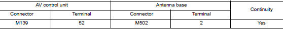
- Check continuity between AV control unit connector M139 and ground.
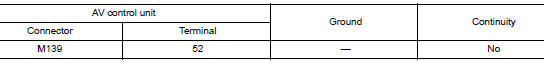
Is the inspection result normal? YES >> GO TO 3.
NO >> Repair or replace harness or connectors.
3.CHECK AV CONTROL UNIT VOLTAGE
- Connect AV control unit connector M139.
- Turn ignition switch ON.
- Check voltage between AV control unit connector M139 and ground.
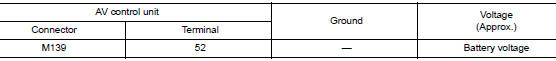
Is the inspection result normal? YES >> Replace antenna base. Refer to AV-392, "Removal and Installation".
NO >> Replace AV control unit. Refer to AV-376, "Removal and Installation".
U12AC AV CONTROL UNIT
DTC Logic
DTC DETECTION LOGIC
|
CONSULT Display |
DTC Detection Condition |
Possible Cause |
| Display Temperature too High [U12AC] | Display temperature has exceeded maximum temperature. Display is switched OFF to avoid irreversible damage. | Replace AV control unit if malfunction occurs
constantly. Refer to AV-376, "Removal and Installation". |
U12AD AV CONTROL UNIT
DTC Logic
DTC DETECTION LOGIC
|
CONSULT Display |
DTC Detection Condition |
Possible Cause |
| ECU Temperature too High [U12AD] | AV control unit temperature has exceeded maximum temperature. | Replace AV control unit if malfunction occurs
constantly. Refer to AV-376, "Removal and Installation". |
U12AE AV CONTROL UNIT
DTC Logic
DTC DETECTION LOGIC
|
CONSULT Display |
DTC Detection Condition |
Possible Cause |
| Internal Amplifier temperature Warning [U12AE] | Internal amplifier temperature has exceeded maximum temperature. | Replace AV control unit if malfunction occurs
constantly. Refer to AV-376, "Removal and Installation". |
U12AF AV CONTROL UNIT
DTC Logic
DTC DETECTION LOGIC
|
CONSULT Display |
DTC Detection Condition |
Possible Cause |
| CD Mechanism Temperature Warning [U12AF] | CD drive temperature has exceeded maximum temperature. CD drive is switched OFF to avoid irreversible damage. | Replace AV control unit if malfunction occurs
constantly. Refer to AV-376, "Removal and Installation". |
U12B0 POWER SUPPLY VOLTAGE
DTC Logic
DTC DETECTION LOGIC
|
CONSULT Display |
DTC Detection Condition |
Possible Cause |
| Supply Voltage Goes below 9V > 20s [U12B0] | AV control unit supply voltage exceeds lower limits. |
|
Diagnosis Procedure
1.CHECK CHARGING SYSTEM
Check the vehicle charging system. Refer to CHG-11, "Work Flow (With EXP-800 NI or GR8-1200 NI)" or CHG-14, "Work Flow (Without EXP-800 NI or GR8-1200 NI)".
Is the inspection result normal? YES >> GO TO 2.
NO >> Repair or replace the malfunctioning components.
2.CHECK AV CONTROL UNIT POWER SUPPLY AND GROUND CIRCUITS
Perform the AV control unit power supply and ground circuit diagnosis procedure. Refer to AV-337, "AV CONTROL UNIT : Diagnosis Procedure".
Is the inspection result normal? YES >> Replace the AV control unit. Refer to AV-376, "Removal and Installation".
NO >> Repair or replace harness or connectors.
U12B1 POWER SUPPLY VOLTAGE
DTC Logic
DTC DETECTION LOGIC
|
CONSULT Display |
DTC Detection Condition |
Possible Cause |
| Supply Voltage Goes High > 16V for 20s [U12B1] | Supply Voltage Goes High > 16V for 20s [U12B1] | Charging system malfunction |
Diagnosis Procedure
1.CHECK CHARGING SYSTEM
Check the vehicle charging system. Refer to CHG-11, "Work Flow (With EXP-800 NI or GR8-1200 NI)" or CHG-14, "Work Flow (Without EXP-800 NI or GR8-1200 NI)".
Is the inspection result normal? YES >> Replace the AV control unit. Refer to AV-376, "Removal and Installation".
NO >> Repair or replace the malfunctioning components.
U1300 AV COMM CIRCUIT
DTC Logic
DTC DETECTION LOGIC
|
CONSULT Display |
DTC Detection Condition |
Possible Cause |
| AV COMM CIRCUIT [U1300] | AV communication circuit malfunction (MCAN) between AV control unit and combination meter. | AV communication circuits between AV control unit and combination meter. |
Diagnosis Procedure
1.PERFORM SELF DIAGNOSTIC RESULT FOR METER M&A
- Turn ignition switch ON and wait for 2 seconds or more.
- Perform “Self Diagnostic Result” for “METER M&A”.
Are any DTCs displayed? YES >> Refer to MWI-30, "DTC Index".
NO >> GO TO 2.
2.CHECK AV COMMUNICATION CIRCUIT (MCAN L) CONTINUITY
- Turn ignition switch OFF.
- Disconnect AV control unit connector M109 and combination meter connector M77.
- Check continuity between AV control unit connector M109 and combination meter connector M77.
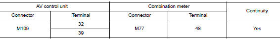
- Check continuity between AV control unit connector M109 and ground.

Is the inspection result normal? YES >> GO TO 3.
NO >> Repair or replace harness or connectors.
3.CHECK AV COMMUNICATION CIRCUIT (MCAN H) CONTINUITY
- Check continuity between AV control unit connector M109 and combination meter connector M77.
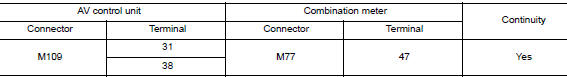
- Check continuity between AV control unit connector M109 and ground.
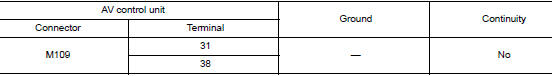
Is the inspection result normal? YES >> Replace the AV control unit. Refer to AV-376, "Removal and Installation".
NO >> Repair or replace harness or connectors.
U1304 CAMERA IMAGE CALIBRATION
DTC Logic
DTC DETECTION LOGIC
|
CONSULT Display |
DTC Detection Condition |
Possible Cause |
| Non-completion of the calibration [U1304] | Camera image calibration is incomplete. | Perform calibration of camera image. |
Diagnosis Procedure
1.PERFORM CALIBRATION
When U1304 is detected, perform calibration of camera image.
>> Refer to AV-292, "CALIBRATING CAMERA IMAGE (AROUND VIEW MONITOR) : Work Procedure".
U1305 CONFIG UNFINISH
DTC Logic
DTC DETECTION LOGIC
|
CONSULT Display |
DTC Detection Condition |
Possible Cause |
| Non-completion of the configuration [U1305] | Configuration of around view monitor control unit is incomplete. | Perform configuration of around view monitor control unit. |
Diagnosis Procedure
1.PERFORM CONFIGURATION
When U1305 is detected, perform configuration of around view monitor control unit.
>> Refer to AV-290, "CONFIGURATION (AROUND VIEW MONITOR CONTROL UNIT) : Work Procedure".
U1310 CONTROL UNIT (AV)
DTC Logic
DTC DETECTION LOGIC
|
CONSULT Display |
DTC Detection Condition |
Possible Cause |
| CONTROL UNIT (AV) [U1310] | Error during CAN controller hardware initialization (MCAN). | Replace AV control unit if malfunction occurs
constantly. Refer to AV-376, "Removal and Installation". |
POWER SUPPLY AND GROUND CIRCUIT
AV CONTROL UNIT
AV CONTROL UNIT : Diagnosis Procedure
Regarding Wiring Diagram information, refer to AV-262, "Wiring Diagram".
1.CHECK FUSE
Check that the following fuses are not blown.
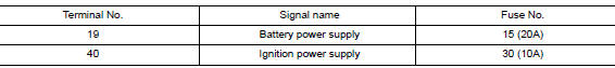
Are the fuses blown? YES >> Replace the blown fuse after repairing the affected circuit.
NO >> GO TO 2.
2.CHECK POWER SUPPLY CIRCUIT
- Turn ignition switch OFF.
- Disconnect AV control unit connectors M108 and M109.
- Check voltage between AV control unit connectors M108 and M109 and ground.
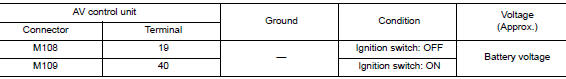
Is the inspection result normal? YES >> GO TO 3.
NO >> Repair or replace harness or connectors.
3.CHECK GROUND CIRCUIT
- Turn ignition switch OFF.
- Check continuity between AV control unit connector M108 and ground.
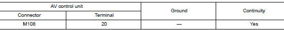
Is the inspection result normal? YES >> Inspection End.
NO >> Repair or replace harness or connectors.
BOSE SPEAKER AMP
BOSE SPEAKER AMP : Diagnosis Procedure
Regarding Wiring Diagram information, refer to AV-262, "Wiring Diagram".
1.CHECK FUSE
Check that the following fuses are not blown.

Are the fuses blown? YES >> Replace the blown fuse after repairing the affected circuit.
NO >> GO TO 2.
2.CHECK POWER SUPPLY CIRCUIT
- Turn ignition switch OFF.
- Disconnect Bose speaker amp. connector B137.
- Check voltage between Bose speaker amp. connector B137 and ground.
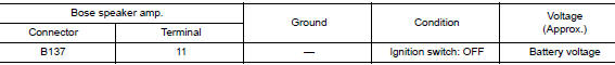
Is the inspection result normal? YES >> GO TO 3.
NO >> Repair or replace harness or connectors.
3.CHECK GROUND CIRCUIT
Check continuity between Bose speaker amp. connector B137 and ground.
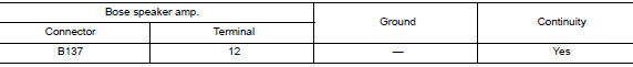
Is the inspection result normal? YES >> Inspection End.
NO >> Repair or replace harness or connectors.
AROUND VIEW MONITOR CONTROL UNIT
AROUND VIEW MONITOR CONTROL UNIT : Diagnosis Procedure
Regarding Wiring Diagram information, refer to AV-262, "Wiring Diagram".
WITHOUT DRIVER ASSISTANCE SYSTEM
1.CHECK FUSE
Check that the following fuses are not blown.

Are the fuses blown? YES >> Replace the blown fuse after repairing the affected circuit.
NO >> GO TO 2.
2.CHECK POWER SUPPLY CIRCUIT
- Turn ignition switch OFF.
- Disconnect around view monitor control unit connector M103.
- Check voltage between around view monitor control unit connector M103 and ground.
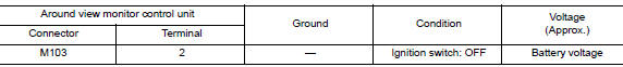
Is the inspection result normal? YES >> GO TO 3.
NO >> Repair or replace harness or connectors.
3.CHECK GROUND CIRCUIT
- Turn ignition switch OFF.
- Check continuity between around view monitor control unit connector M103 and ground.
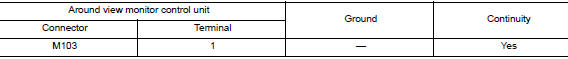
Is the inspection result normal? YES >> Inspection End.
NO >> Repair or replace harness or connectors.
WITH DRIVER ASSISTANCE SYSTEM
1.CHECK FUSE
Check that the following fuses are not blown.

Are the fuses blown? YES >> Replace the blown fuse after repairing the affected circuit.
NO >> GO TO 2.
2.CHECK POWER SUPPLY CIRCUIT
- Turn ignition switch OFF.
- Disconnect around view monitor control unit connector M113.
- Check voltage between around view monitor control unit connector M113 and ground.
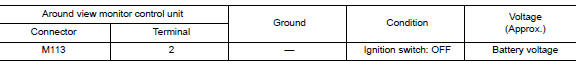
Is the inspection result normal? YES >> GO TO 3.
NO >> Repair or replace harness or connectors.
3.CHECK GROUND CIRCUIT
- Turn ignition switch OFF.
- Check continuity between around view monitor control unit connector M113 and ground.
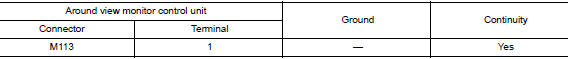
Is the inspection result normal? YES >> Inspection End.
NO >> Repair or replace harness or connectors.
FRONT TWEETER
Diagnosis Procedure
Regarding Wiring Diagram information, refer to AV-262, "Wiring Diagram".
1.CONNECTOR CHECK
Check the AV control unit, Bose speaker amp. and speaker connectors for the following:
- Proper connection
- Damage
- Disconnected or loose terminals
Is the inspection result normal? YES >> GO TO 2.
NO >> Repair the terminals or connectors.
2.CHECK FRONT TWEETER SIGNAL CIRCUIT CONTINUITY (BOSE SPEAKER AMP.)
- Disconnect Bose speaker amp. connectors and suspect front tweeter connector.
- Check continuity between Bose speaker amp. connectors and suspect front tweeter connector.
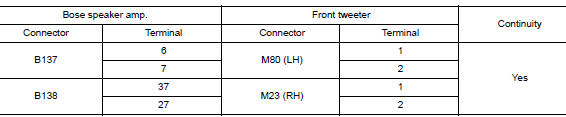
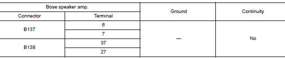
- Check continuity between Bose speaker amp. connectors and ground.
Is the inspection result normal? YES >> GO TO 3.
NO >> Repair or replace harness or connectors.
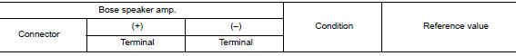
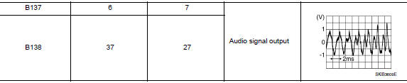
3.CHECK FRONT TWEETER SIGNAL (BOSE SPEAKER AMP.)
- Connect Bose speaker amp. connectors and suspect front tweeter connector.
- Turn ignition switch to ON.
- Push AV control unit POWER switch.
- Check signal between the terminals of Bose speaker amp. connectors.
Is the inspection result normal? YES >> Replace front tweeter. Refer to AV-380, "Removal and Installation".
NO >> GO TO 4.
4.CHECK FRONT TWEETER SIGNAL CIRCUIT CONTINUITY (AV CONTROL UNIT)
- Turn ignition switch to OFF.
- Disconnect Bose speaker amp. connector B138 and AV control unit connector M108
- Check continuity between Bose speaker amp. connector B138 and AV control unit connector M108.
- Check continuity between Bose speaker amp. connector B138 and ground.
Is the inspection result normal? YES >> GO TO 5.
NO >> Repair or replace harness or connectors.
5.CHECK FRONT TWEETER SIGNAL (AV CONTROL UNIT)
- Connect Bose speaker amp. connector B138 and AV control unit connector M108.
- Turn ignition switch to ON.
- Push AV control unit POWER switch.
- Check signal between AV control unit connector M108 and ground.
Is the inspection result normal?
YES >> Replace Bose speaker amp. Refer to AV-379, "Removal and Installation".
NO >> Replace AV control unit. Refer to AV-376, "Removal and Installatio
 Basic inspection
DIAGNOSIS AND REPAIR WORKFLOW
Work Flow
OVERALL SEQUENCE
DETAILED FLOW
1.GET INFORMATION FOR SYMPTOM
Get detailed information from the customer about the symptom (the condition
and the envi ...
 Symptom diagnosis
MULTI AV SYSTEM
Symptom Table
RELATED TO AUDIO
RELATED TO HANDS-FREE PHONE
Before performing diagnosis, confirm that the cellular phone being
used by the customer is co ...
Other materials:
Precaution
Precaution for Supplemental Restraint System (SRS) "AIR BAG" and "SEAT
BELT
PRE-TENSIONER"
The Supplemental Restraint System such as “AIR BAG” and “SEAT BELT PRE-TENSIONER”,
used along
with a front seat belt, helps to reduce the risk or severity of injury to the
...
Rear window defogger relay
Description
Power is supplied to the rear window defogger with BCM control.
Component Function Check
1. CHECK REAR WINDOW DEFOGGER RELAY POWER SUPPLY CIRCUIT
Check that an operation noise of rear window defogger relay [located in fuse
block (J/B)] can be heard when
turning the rear window def ...
Idle air volume learning
Description
Idle Air Volume Learning is a function of ECM to learn the idle air volume
that keeps each engine idle speed
within the specific range. It must be performed under any of the following
conditions:
Each time electric throttle control actuator or ECM is replaced.
Idle spee ...
