Nissan Rogue Service Manual: P0078 EVT control solenoid valve
DTC Description
DTC DETECTION LOGIC
| DTC No. | CONSULT screen terms (Trouble diagnosis content) | DTC detecting condit |
| P0078 | EX V/T ACT/CIRC-B1 (Exhaust valve control solenoid circuit bank 1) | An improper voltage is sent to the ECM through exhaust valve timing control solenoid valve. |
POSSIBLE CAUSE
- Harness or connectors (Exhaust valve timing control solenoid valve circuit is open or shorted.)
- Exhaust valve timing control solenoid valve
FAIL-SAFE
Device fix mode
DTC CONFIRMATION PROCEDURE
1.PRECONDITIONING
If DTC Confirmation Procedure has been previously conducted, always perform the following procedure before conducting the next test.
- Turn ignition switch OFF and wait at least 10 seconds.
- Turn ignition switch ON.
- Turn ignition switch OFF and wait at least 10 seconds.
>> GO TO2.
2.PERFORM DTC CONFIRMATION PROCEDURE
- Start engine and let it idle for 5 seconds.
- Check 1st trip DTC.
Is 1st trip DTC detected? YES >> Proceed to EC-195, "Diagnosis Procedure".
NO >> INSPECTION END
Diagnosis Procedure
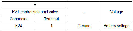
1.CHECK EXHAUST VALVE TIMING CONTROL SOLENOID VALVE POWER SUPPLY
- Turn ignition switch OFF.
- Disconnect exhaust valve timing (EVT) control solenoid valve harness connector.
- Turn ignition switch ON.
- Check the voltage between exhaust valve timing control solenoid valve harness connector and ground.
Is the inspection result normal? YES >> GO TO 3.
NO >> GO TO 2.
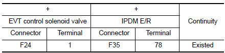
2.CHECK EXHAUST VALVE TIMING CONTROL SOLENOID VALVE POWER SUPPLY CIRCUIT
- Turn ignition switch OFF.
- Disconnect IPDM E/R harness connector.
- Check the continuity between EVT control solenoid valve harness connector and IPDM E/R harness connector.
- Also check harness for short to ground.
Is the inspection result normal? YES >> Perform the trouble diagnosis for power supply circuit.
NO >> Repair or replace error-detected parts.
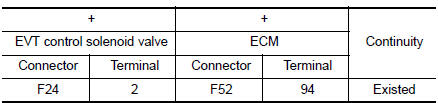
3.CHECK EXHAUST VALVE TIMING CONTROL SOLENOID VALVE GROUND CIRCUIT
- Turn ignition switch OFF.
- Disconnect ECM harness connector.
- Check the continuity between EVT control solenoid valve harness connector and ECM harness connector.
- Also check harness for short to ground and to power.
Is the inspection result normal? YES >> GO TO 4.
NO >> Repair or replace error-detected parts.
4.CHECK EXHAUST VALVE TIMING CONTROL SOLENOID VALVE
Check the exhaust valve timing control solenoid valve. Refer to EC-183, "Component Inspection".
Is the inspection result normal? YES >> GO TO 5.
NO >> Replace exhaust valve timing control solenoid valve.
5.CHECK INTERMITTENT INCIDENT
Refer to GI-41, "Intermittent Incident".
>> INSPECTION END
Component Inspection
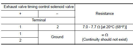
1.CHECK EXHAUST VALVE TIMING CONTROL SOLENOID VALVE-1
- Turn ignition switch OFF.
- Disconnect exhaust valve timing control solenoid valve harness connector.
- Check resistance between exhaust valve timing control solenoid valve terminals as per the following.
Is the inspection result normal?
YES >> GO TO 2.
NO >> Replace exhaust valve timing control solenoid valve. Refer to EM-44, "Exploded View".
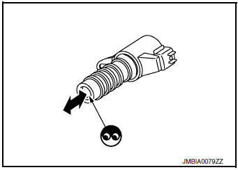
2.CHECK EXHAUST VALVE TIMING CONTROL SOLENOID VALVE-2
- Remove exhaust valve timing control solenoid valve. Refer to EM-44, "Exploded View".
- Provide 12 V DC between exhaust valve timing control solenoid valve terminals 1 and 2, and then interrupt it. Check that the plunger moves as shown in the figure.
CAUTION: Do not apply 12 V DC continuously for 5 seconds or more.
Doing so may result in damage to the coil in exhaust valve timing control solenoid valve.
NOTE: Always replace O-ring when exhaust valve timing control solenoid valve is removed.
Is the inspection result normal? YES >> INSPECTION END
NO >> Replace exhaust valve timing control solenoid valve. Refer to EM-44, "Exploded View".
 P0075 intake valve timing control
DTC Description
DTC DETECTION LOGIC
DTC No.
CONSULT screen terms
(Trouble diagnosis content)
DTC detecting condition
P0075
INT/V TIM V/CIR-B1
(Intake valve control sol ...
 P0101 MAF sensor
DTC Description
DTC DETECTION LOGIC
DTC No.
CONSULT screen terms
(Trouble diagnosis content)
DTC detecting condition
P0101
MAF SEN/CIRCUIT-B1
(Mass or volume air Flow ...
Other materials:
Wiring diagram
POWER DISTRIBUTION SYSTEM
Wiring Diagram
...
Interior room lamp control circuit
Description
Controls each interior room lamp (ground side) by PWM signal.
NOTE:
PWM signal control period is approximately 250 Hz (in the gradual
brightening/dimming).
Component Function Check
CAUTION:
Before performing the diagnosis, check that the following is normal.
Interior ro ...
Parking brake front cable
Removal and Installation
REMOVAL
Remove the instrument lower panel LH. Refer to IP-22, "Removal and
Installation".
Remove driver seat (LH). Refer to SE-32, "DRIVER SIDE : Removal
and Installation"
Remove the center console. Refer to IP-18, "R ...
