Nissan Rogue Service Manual: Wiring diagram
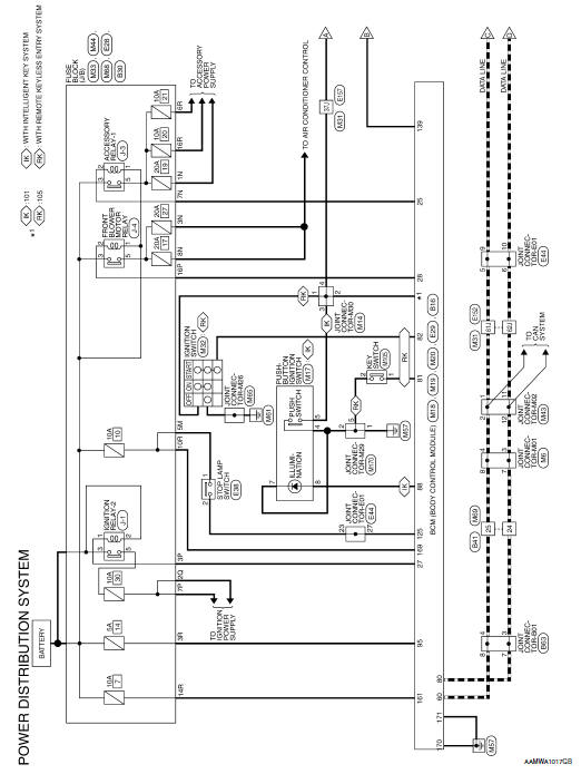
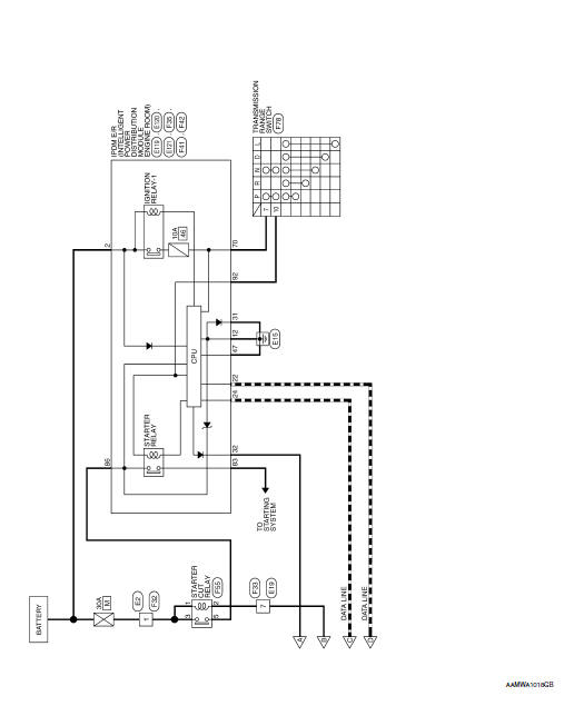
POWER DISTRIBUTION SYSTEM
Wiring Diagram
 ECU diagnosis information
BCM
List of ECU Reference
...
 Basic inspection
DIAGNOSIS AND REPAIR WORK FLO
Work Flow
OVERALL SEQUENCE
DETAILED FLOW
1.GET INFORMATION FOR SYMPTOM
Get detailed information from the customer about the symptom (the
condition an ...
Other materials:
DTC/circuit diagnosis
B2600-46 CONFIG ERROR
DTC Description
DTC DETECTION LOGIC
DTC
Trouble diagnosis
(Trouble diagnosis contents)
Detecting condition
B2600-46
CONFIG ERROR
(Configuration error)
When errors are detected in the configuration data stored in the BCM
(CAN
...
Unit disassembly and assembly
FRONT DRIVE SHAFT
Exploded View (LH)
Shaft
Circular clip
Dust shield
Housing
Snap ring
Spider assembly
Stopper ring
Boot
Boot band
Joint sub-assembly
Wheel side
Disassembly and Assembly (LH)
DISASSEMBLY
Transaxle Assembly Side
Fix shaft ...
EPS warning lamp
Component Function Check
1.CHECK THE ILLUMINATION OF THE EPS WARNING LAMP
Check that the EPS warning lamp turns ON when ignition switch turns ON. Then,
EPS warning lamp turns
OFF after the engine is started.
Is the inspection result normal?
YES >> Inspection End.
NO >> Perfor ...
