Nissan Rogue Service Manual: Basic inspection
DIAGNOSIS AND REPAIR WORK FLO
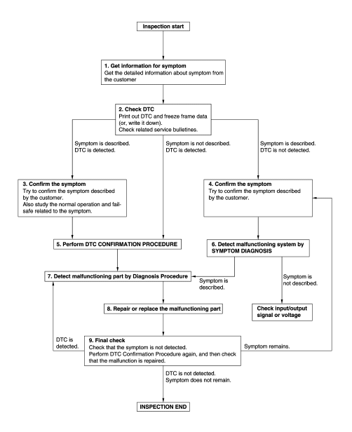
Work Flow
OVERALL SEQUENCE
DETAILED FLOW
1.GET INFORMATION FOR SYMPTOM
- Get detailed information from the customer about the symptom (the condition and the environment when the incident/malfunction occurs).
- Check operation condition of the component or system that is malfunctioning.
>> GO TO 2.
2.CHECK DTC
- Check DTC.
- Perform the following procedure if DTC is detected.
- Record DTC and freeze frame data (Print them out using CONSULT).
- Erase DTC.
- Study the relationship between the cause detected by DTC and the symptom described by the customer.
- Check related service bulletins for information.
Are any symptoms described and any DTC detected? Symptom is described, DTC is detected>>GO TO 3.
Symptom is described, DTC is not detected>>GO TO 4.
Symptom is not described, DTC is detected>>GO TO 5.
3.CONFIRM THE SYMPTOM
Try to confirm the symptom described by the customer.
Also study the normal operation and fail-safe related to the symptom.
Verify relation between the symptom and the condition when the symptom is detected.
>> GO TO 5.
4.CONFIRM THE SYMPTOM
Try to confirm the symptom described by the customer.
Verify relation between the symptom and the condition when the symptom is detected.
NOTE: Freeze frame data is useful if the DTC is not detected.
>> GO TO 6.
5.PERFORM DTC CONFIRMATION PROCEDURE
Perform DTC CONFIRMATION PROCEDURE for the detected DTC, and then check that DTC is detected again. At this time, always connect CONSULT to the vehicle, and check self diagnostic results in real time.
If two or more DTCs are detected, refer to BCS-47, "DTC Inspection Priority Chart", and determine trouble diagnosis order.
Is DTC detected? YES >> GO TO 7.
NO >> Refer to GI-41, "Intermittent Incident".
6.DETECT MALFUNCTIONING SYSTEM BY SYMPTOM DIAGNOSIS
Detect malfunctioning system according to SYMPTOM DIAGNOSIS based on the confirmed symptom in step 4, and determine the trouble diagnosis order based on possible causes and symptom.
Is the symptom described? YES >> GO TO 7.
NO >> Monitor input data from related sensors or check voltage of related module terminals using CONSULT.
7.DETECT MALFUNCTIONING PART BY DIAGNOSIS PROCEDURE
Inspect according to Diagnosis Procedure of the system.
Is malfunctioning part detected? YES >> GO TO 8.
NO >> Refer to GI-41, "Intermittent Incident".
8.REPAIR OR REPLACE THE MALFUNCTIONING PART
- Repair or replace the malfunctioning part.
- Reconnect parts or connectors disconnected during Diagnosis Procedure again after repair and replacement.
- Check DTC. If DTC is detected, erase it.
>> GO TO 9.
9.FINAL CHECK
When DTC is detected in step 2, perform DTC CONFIRMATION PROCEDURE again, and then check that the malfunction is repaired securely.
When symptom is described by the customer, refer to confirmed symptom in step 3 or 4, and check that the symptom is not detected.
Is DTC detected and does symptom remain? YES-1 >> DTC is detected: GO TO 7.
YES-2 >> Symptom remains: GO TO 4.
NO >> Inspection End.
 Wiring diagram
POWER DISTRIBUTION SYSTEM
Wiring Diagram
...
 DTC/circuit diagnosis
U1000 CAN COMM CIRCUIT
WITH INTELLIGENT KEY
WITH INTELLIGENT KEY : Description
Refer to LAN-8, "System Description".
WITH INTELLIGENT KEY : DTC Logic
DTC DETECTION LOGIC
NOTE:
U1000 c ...
Other materials:
Booster seats
Precautions on booster seats
WARNINGIf a booster seat and seat belt are not used
properly, the risk of a child being injured in
a sudden stop or collision greatly
increases:
Make sure the shoulder portion of
the belt is away from the child’s face
and neck and ...
Power window retained power operation does not operate
properly
Diagnosis Procedure
1.CHECK DOOR SWITCH
Check door switch.
Refer to DLK-149, "Component Function Check" (with Intelligent Key system) or
DLK-319,
"Component Function Check" (without Intelligent Key system).
Is the inspection result normal?
YES >> GO TO 2.
NO ...
System description
COMPONENT PARTS
Component Parts Location
Air bag diagnosis sensor unit
AV control unit
Around view monitor control unit
Chassis control module
ABS actuator and electric unit (control
unit)
• A/C auto amp. (With auto A/C)
• Front air control (Without auto A/
C)
...
