Nissan Rogue Service Manual: System description
COMPONENT PARTS
Component Parts Location
- Air bag diagnosis sensor unit
- AV control unit
- Around view monitor control unit
- Chassis control module
- ABS actuator and electric unit (control unit)
- • A/C auto amp. (With auto A/C)
• Front air control (Without auto A/ C) - TCM 8. Distance sensor 9. ECM
- IPDM E/R 11. EPS control unit 12. Data link connector
- BCM 14. Combination meter 15. Steering angle sensor
- AWD control unit 17. Automatic back door control module
SYSTEM
CAN COMMUNICATION SYSTEM
CAN COMMUNICATION SYSTEM : System Description
SYSTEM DIAGRAM
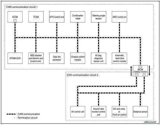
DESCRIPTION
- CAN (Controller Area Network) is a serial communication line for real time application. It is an on-vehicle multiplex communication line with high data communication speed and excellent error detection ability. Many electronic control units are equipped onto a vehicle, and each control unit shares information and links with other control units during operation (not independent). In CAN communication, control units are connected with 2 communication lines (CAN-H line, CAN-L line) allowing a high rate of information transmission with less wiring. Each control unit transmits/receives data but selectively reads required data only.
- The following control units include a gateway function and communicate signals between the different CAN communication circuits.

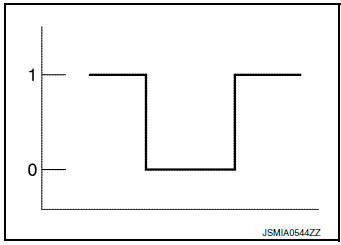
CAN Communication Signal Generation
- Termination circuits (resistors) are connected across the CAN communication system. When transmitting a CAN communication signal, each control unit passes a current to the CAN-H line and the current returns to the CAN-L line.
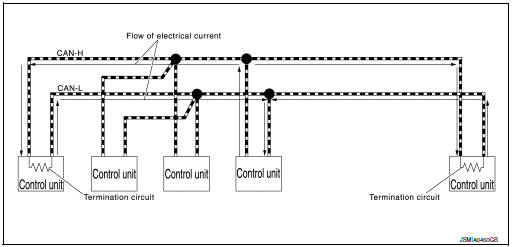
- The current flows separately into the termination circuits connected
across the CAN communication system and the termination circuits
drop voltage to generate a potential difference between the
CAN-H line and the CAN-L line.
NOTE: A signal with no current passage is called “Recessive” and one with current passage is called “Dominant”.
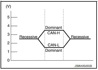
- The system produces digital signals for signal communications, by using the potential difference.
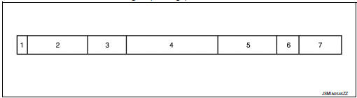
The Construction of CAN Communication Signal (Message)
|
No. |
Message name |
Description |
| 1 | Start of frame (1 bit) | Start of message. |
| 2 | Arbitration of field (11 bit) | Priorities of message-sending are shown when there is a possibility that multiple messages are sent at the same time. |
| 3 | Control field (6 bit) | Signal quantity in data field is shown. |
| 4 | Data field (0-64 bit) | Actual signal is shown. |
| 5 | CRC field (16 bit) |
|
| 6 | ACK field (2 bit) | The completion of normal reception is sent to the transmitting unit. |
| 7 | End of frame (7 bit) | End of message. |
CAN Communication Line
The CAN communication line is a twisted pair wire consisting of strands of CAN-H 1 and CAN-L 2 and has noise immunity.
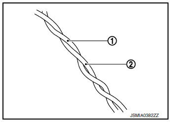
NOTE: The CAN communication system has the characteristics of noise-resistant because this system produces digital signals by using the potential difference between the CAN-H line and the CAN-L line and has the twisted pair wire structure.
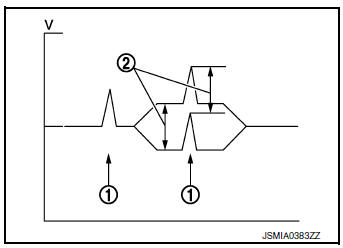
Since the CAN-H line and the CAN-L line are always adjacent to each other, the same degree of noise occurs, respectively, when a noise 1 occurs. Although the noise changes the voltage, the potential difference 2 between the CAN-H line and the CAN-L line is insensitive to noise. Therefore, noise-resistant signals can be obtained.
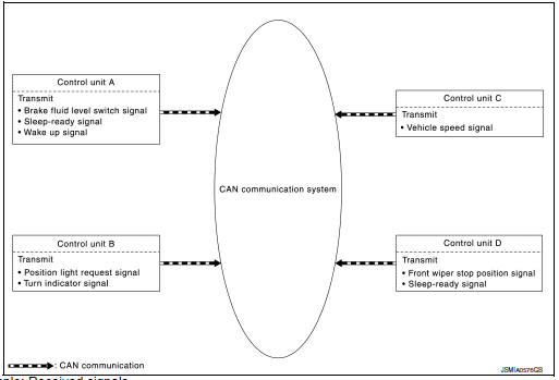
CAN Signal Communications
Each control unit of the CAN communication system transmits signals through the CAN communication control circuit included in the control unit and receives only necessary signals from each control unit to perform various kinds of control.
- Example: Transmitted signals
- Example: Received signals
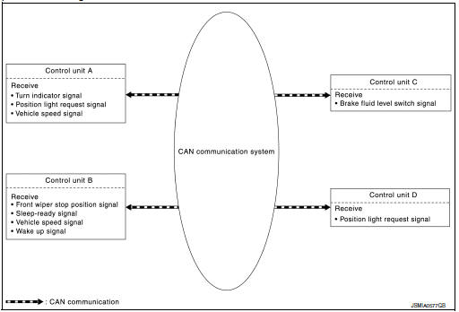
NOTE: The above signal names and signal communications are provided for reference purposes. For CAN communications signals of this vehicle, refer to LAN-32, "CAN COMMUNICATION SYSTEM : CAN Communication Signal Chart".
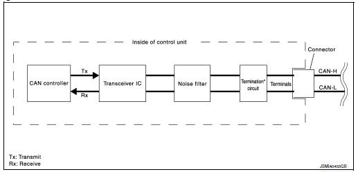
CAN COMMUNICATION SYSTEM : CAN Communication Control Circuit
CAN communication control circuit is incorporated into the control unit and transmits/receives CAN communication signals.
|
Component |
System description |
| CAN controller | It controls CAN communication signal transmission and reception, error detection, etc. |
| Transceiver IC | It converts digital signal into CAN communication signal, and CAN communication signal into digital signal. |
| Noise filter | It eliminates noise of CAN communication signal. |
| Termination circuit* (Resistance of approx. 120 Ω) | Generates a potential difference between CAN-H and CAN-L. |
*: These are the only control units wired with both ends of CAN communication system.
CAN COMMUNICATION SYSTEM : CAN System Specification Chart
Determine CAN system type from the following specification chart.
NOTE: Refer to LAN-17, "Trouble Diagnosis Procedure" for how to use CAN system specification chart.
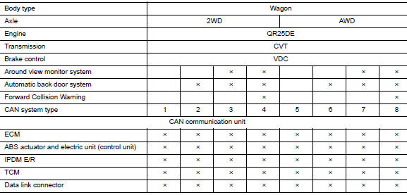
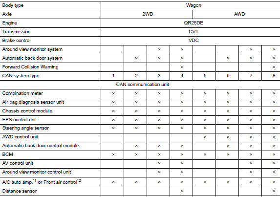
Ă—: Applicable
*1: With auto A/C
*2: Without auto A/C
VEHICLE EQUIPMENT IDENTIFICATION INFORMATION
NOTE: Check CAN system type from the vehicle shape and equipment.
- Door mirror LH side camera
- Automatic back door main switch
- Warning systems switch
- With around view monitor system
- With automatic back door system
- With forward collision warning
CAN COMMUNICATION SYSTEM : CAN Communication Signal Chart
Refer to LAN-16, "How to Use CAN Communication Signal Chart" for how to use CAN communication signal chart.
NOTE: Refer to LAN-22, "Abbreviation List" for the abbreviations of the connecting units.
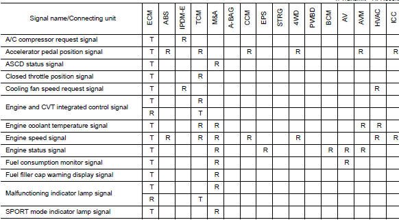
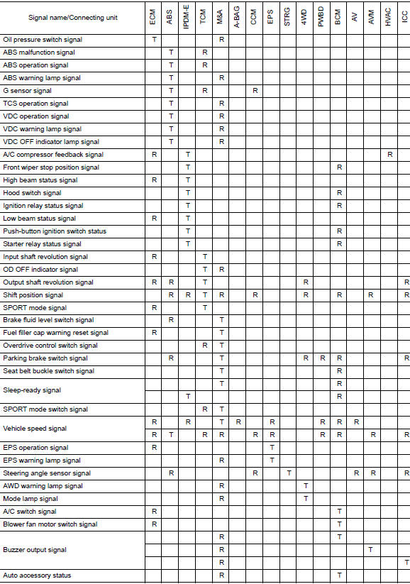
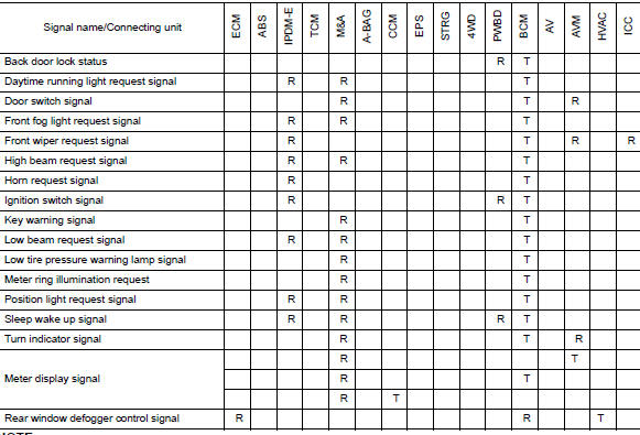
NOTE: CAN data of the air bag diagnosis sensor unit is not used by usual service work, thus it is omitted.
 Precaution
Precaution for Supplemental Restraint System (SRS) "AIR BAG" and "SEAT
BELT
PRE-TENSIONER"
The Supplemental Restraint System such as “AIR BAG” and “SEAT BELT PRE-TENSIONE ...
 Wiring diagram
CAN SYSTEM
Wiring Diagram - CAN SYSTEM -
...
Other materials:
Maximum load limits
Never allow the total trailer load to exceed the
value specified in the “Towing
Load/Specification” chart found in this section.
The total trailer load equals trailer weight plus its
cargo weight.
The maximum Gross Combined Weight Rating
(GCWR) should not exceed the value specified
in ...
Symptom diagnosis
AUDIO SYSTEM
Symptom Table
RELATED TO AUDIO
Symptoms
Check items
Probable malfunction location
The disk cannot be removed
Audio unit
Malfunction in audio unit.
Refer to AV-18, "On Board Diagnosis Function".
No sound comes out or the le ...
P0890 TCM
DTC Description
DTC DETECTION LOGIC
DTC
CONSULT screen terms
(Trouble diagnosis content)
DTC detection condition
P0890
TCM
(Transmission Control Module Power Relay
Sense Circuit Low)
When all of the following conditions are satisfied and this state is
maint ...
